d. Remove O-ring seals (3) from connectors (2)
and plugs (5).
Installation Procedure (Mechanical
Priming Pump)
NOTICE
Ensure that all adjustments and repairs that are
carried out to the fuel system are performed by
authorized personnel that have the correct
training.
Before beginning ANY work on the fuel system,
refer to Operation and Maintenance Manual, “Gen-
eral Hazard Information and High Pressure Fuel
Lines” for safety information.
Refer to System Operation, Testing and Adjusting,
“Cleanliness of Fuel System Components” for de-
tailed information on the standards of cleanliness
that must be observed during ALL work on the
fuel system.
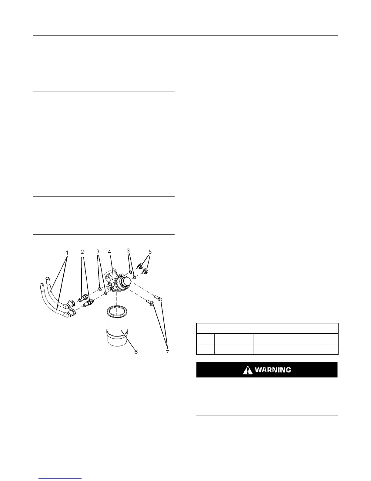
1. Ensure that fuel priming pump (4) is clean and free
from wear or damage. If necessary, replace the
fuel priming pump.
Illustration 2 g02988817
Typical example
2. If necessary, follow Steps 2.a. through 2.f. in order
to assemble fuel priming pump (4).
a. Install new O-ring seals (3) to plugs (5).
b. Remove caps from connectors (2). Install new
O-ring seals (3) connectors (2).
c. Remove plugs from fuel priming pump (4).
d. Install connectors (2) to fuel priming pump (4).
e. Install plugs (5) to fuel priming pump (4).
f. Tighten the plugs and the connectors to a
torque of 20 N·m (14 lb ft).
3. Position fuel priming pump (4) on the mounting
bracket. Install bolts (7) to the fuel priming pump .
Tighten the bolts to a torque of 44 N·m (32 lb ft).
4. Remove the plugs from the plastic tube
assemblies. Remove the caps from the
connectors.
5. Connect plastic tube assemblies (1) to connectors
(2).
Note: Ensure that the plastic tube assemblies are
installed in the original positions.
6. Install a new primary filter (6) to fuel priming pump
(4). Refer to Operation and Maintenance Manual,
“Fuel System Primary Filter (Water Separator)
Element - Replace”.
7. Turn the fuel supply to the ON position.
8. Prime the fuel system. Refer to Operation and
Maintenance Manual, “Fuel System - Prime”.
i06211125
Flow Control Valve - Remove
and Install
Removal Procedure
Table 2
Required Tools
Tool Part Number
Part Description Qty
A T412504
Capping Kit
1
Contact with high pressure fuel may cause fluid
penetration and burn hazards. High pressure fuel
spray may cause a fire hazard. Failure to follow
these inspection, maintenance and service in-
structions may cause personal injury or death.
6 UENR4503
Disassembly and Assembly Section