Chapter 4 N37347
Page 38
How to check the valve tip clearances
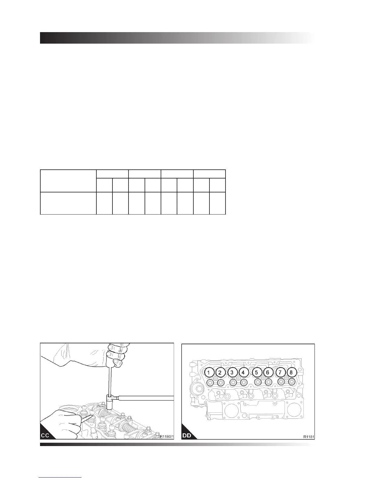
The valve tip clearances are checked between the top of the valve stem and the rocker lever (CC), with the
engine cold. The correct clearance for inlet valves is 0,20 mm (0.008 in) and 0,45 mm (0.018 in) for exhaust
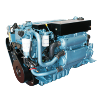
valves. The valve positions are shown at (DD).
The sequence of valves from number 1 cylinder is shown in the table below.
Note: Number 1 cylinder is the furthest cylinder from the ywheel end of the engine.
1. Rotate the crankshaft in the normal direction of rotation until the inlet valve (DD7) of number 4 cylinder
has just opened and the exhaust valve (DD8) of the same cylinder has not closed completely. Check the
clearances of the valves (DD1 and DD2) of number 1 cylinder and adjust them, if necessary.
2. Set the valves (DD3 and DD4) of number 2 cylinder as indicated above for number 4 cylinder. Then
check / adjust the clearances of the valves (DD5 and DD6) of number 3 cylinder.
3. Set the valves (DD1 and DD2) of number 1 cylinder. Then check / adjust the clearances of the valves
(DD7 and DD8) of number 4 cylinder.
4. Set the valves (DD5 and DD6) of number 3 cylinder. Then check / adjust the clearances of the valves
(DD3 and DD4) of number 2 cylinder.
Cylinder
and
valve number
1 2 3 4
1 2 3 4 5 6 7 8
Valve
I = Inlet
E = Exhaust
I E I E I E I E