F5 Corpus Repairs - Seat
4.1.8.2 Mounting armrest height adjustment mechanism
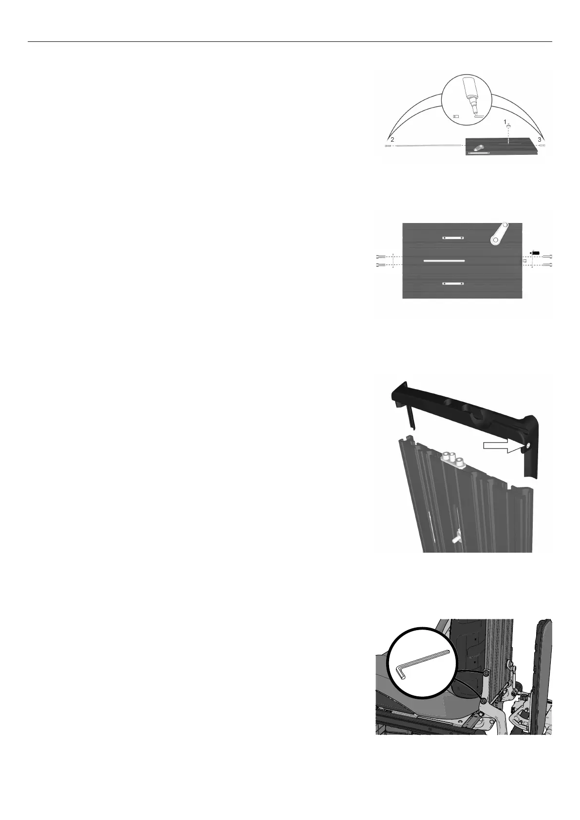
Figure 98. Apply thread locker.
1. Push the threaded rod into the backrest profile and at the same time
screw on the driver (1).
2. Apply thread locker (Loctite 2701) to the ends of the threaded rod
and fit the two end pieces (2 & 3) onto the threaded rod.
Figure 99. The adjustment bar brackets are each held in
place by two screws.
3. Assemble the adjustment bar brackets, which are each held in place
by two screws.
Figure 100. The end cover of the backrest profile is
secured using one screw on the left side and one on the
right.
4. Reassemble the end cover of the backrest profile by pushing it
straight into the end of the profile. Secure the cover by tightening
the screws on the left and right.
Figure 101. The backrest profile is secured by two
screws on the left and right.
5. Reassemble the backrest profile by fitting the hinge and the slewing
bracket into the profile groove on the left and right sides. Slide the
profile downwards until the stop on the bracket and the slewing
bracket is touching the end of the backrest profile on both the left
side and the right. Secure the backrest profile by tightening the two
screws on the left and right. Tighten the screws using a torque
wrench. Tightening torque 7.2 lb.ft.
44
 Loading...