Smart 32 Remote Control Panel User Guide
Publication 81-9059-0727-0, Rev. A
April 2014
Proprietary Information of
PESA 3-2
When a Smart 32 panel is connected to the Ethernet network, it sends a multicast message which
includes its Panel ID number. A system controller receives the multicast message and checks to see if
the Panel ID in the multicast message is in its controller configuration file. If the Panel ID in the
multicast message is found in the configuration, then the system controller sends a multicast message,
which includes the Panel ID, IP for the panel, Netmask, and Gateway. The Smart 32 panel receives the
multicast message from the System Controller and verifies the Panel ID. If the Panel ID is correct, the
panel checks its network parameters (IP, Netmask, and Gateway) with those contained in the received
multicast message. If any network parameter is different, then the panel updates itself using the values
found in the received multicast message. Note that he Smart 32 will not allow a zero to be configured
for the IP, Netmask, or Gateway.
If at any time you wish to change the IP address of a Smart 32 panel, change the address data through
the Cattrax panel configuration pages and re-load the controller configuration file.
3.3 S
MART
32
C
ONTROL
P
ANEL
I
NSTALLATION
• Locate Smart 32 panel in desired area for installation and ensure a connection point to the
facility Ethernet and a source of power are both available.
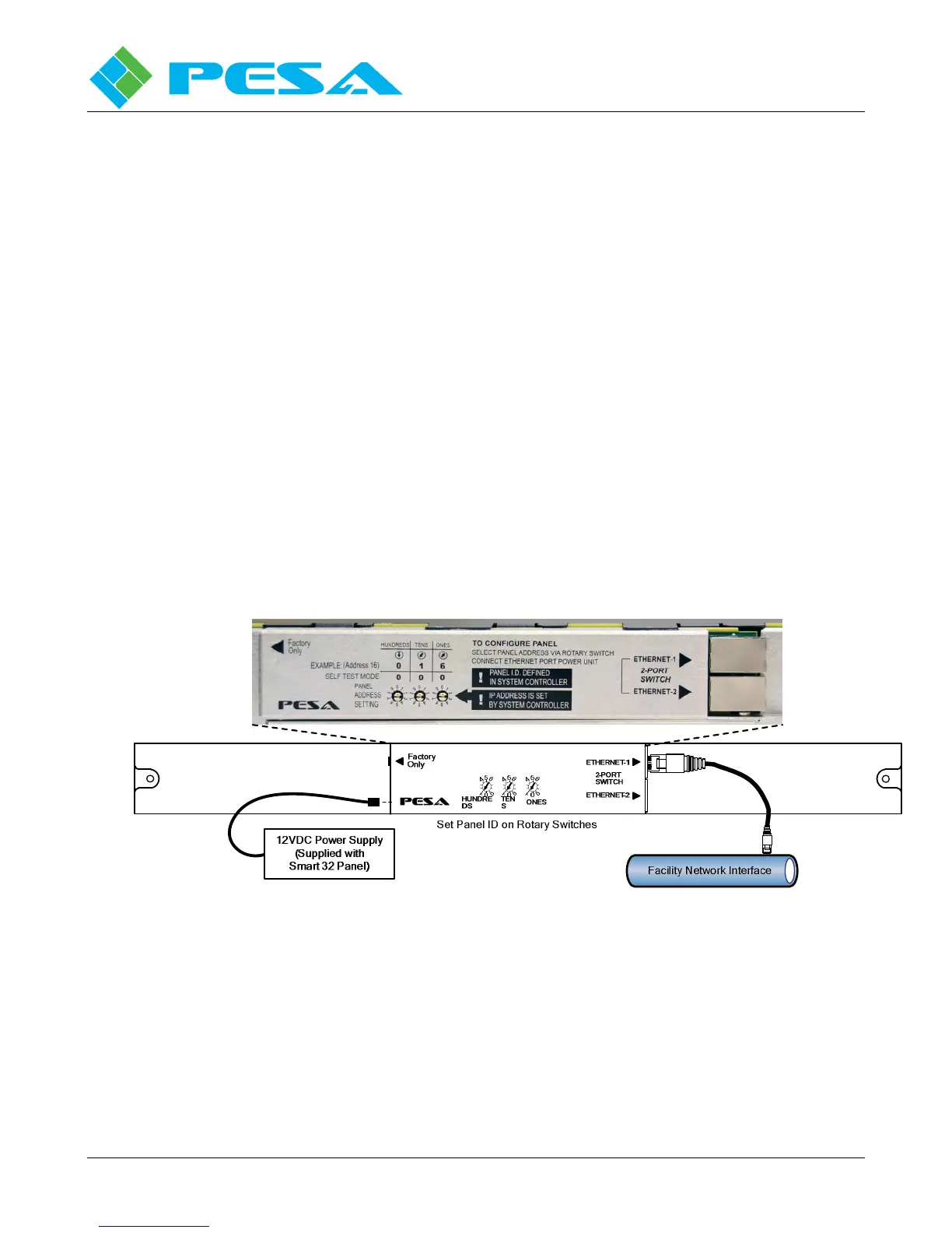
• Using a small screwdriver, set desired Panel ID address on the three rotary switches on the rear
panel as shown by Figure 3-1. Every Smart 32 panel must be assigned a unique panel ID
address. You may use any series of numbers in the range 001 – 999. Panel ID is a required
parameter for control panel configuration as discussed in Paragraph 3.2 of this User Guide.
8
2
7
3
8
2
7
3
8
2
7
3
Figure 3-1 Smart 32 Control Panel (Rear View)
• The connector labeled Factory Only is not used for panel installation and should be left open.
• Install a Cat5 Ethernet cable between either rear panel Ethernet Port (1 or 2) and an Ethernet
hub or switch, or directly to any available facility Ethernet interface drop.


 To Next Page