Adjustment
40
Fig. 1 - 34
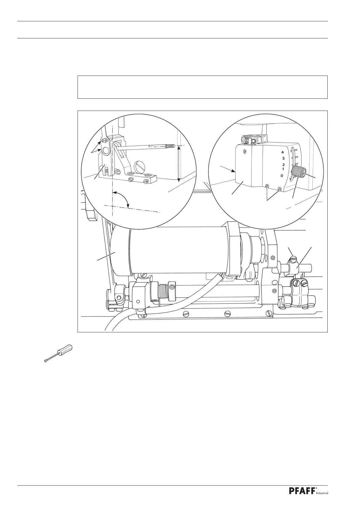
● Unscrew the milled screw of adjustment lever 1 (screw 2).
● Remove cover 3 (screws 4).
● Place crank 5 (screws 6) at right angles to the bed plate, and at the same time set a di-
stance of 65 mm between adjustment lever 1 and the bedplate.
● Screw cover 3 (screws 4) back on.
● Set adjustment lever 1 at "0".
● Remove cover cap 7 and check the lifting motion of the knife by turning the motor impel-
ler wheel (see requirement).
● Adjust crank 8 (screw 9) in accordance with the requirement.
1.06 Adjusting the underedge trimmer -771//05
1
.06.01 Resting position of the knife
Requirement
When adjustment lever 1 is set at "0", the knife stroke should be as small as possible.
6
5
90°
65 mm
4
3
4
2
1
9
8
7