Adjustment
46
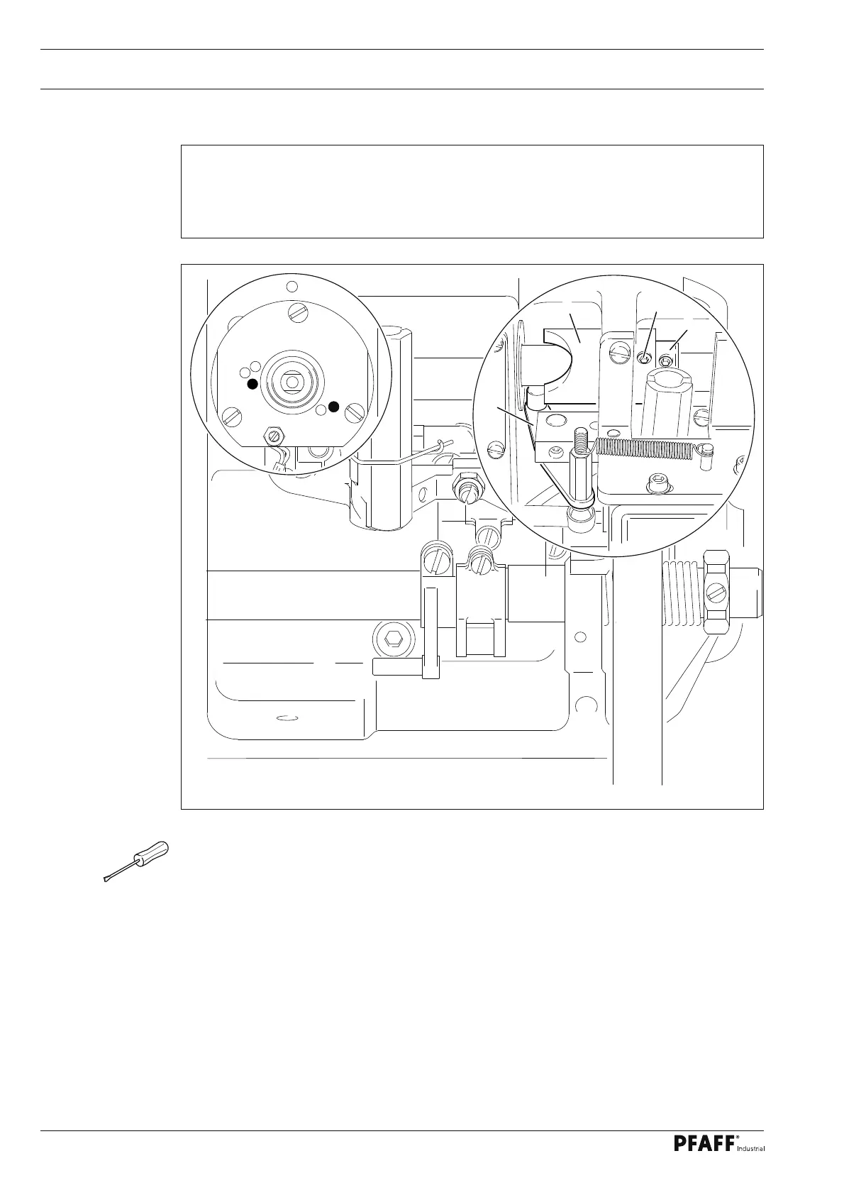
1.07.02 Preliminary adjustment of the control cam
Fig. 1 - 39
● Turn control cam 1 (screws 2) in accordance with requirement 1 and shift it in
accordance with requirement 2.
Requirement
1. In the needle rise position (hole 1) the roller lever 4 should lock into the corresponding
groove of the control cam.
2. The control cam 1 should be touching adjustment ring 3.
1
2
3
4
4
2
5
1
3