Adjustment
48
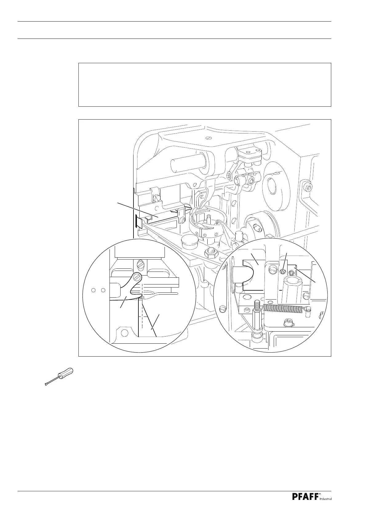
Fig. 1 - 41
1.07.04 Readjustment of the control cam
● Bring the needle bar to b.d.c.
● Turn control cam 1 (screws 2) in accordance with requirement 1 and shift it in accor-
dance with requirement 2.
Requirement
1. When the end of the hook guard 3 is level with of the right edge of the bobbin case
position fi nger 4, the thread catcher 5 should begin moving forwards.
2. The control cam 1 should be touching adjustment ring 6.
5
3
4
2
1
5