EN – 48
Remove 4 nuts (1) then (2).
Insert two screwdrivers into the two notches and twist to remove plate off pins (11).
Pull flange (4) straight out, holding HP rotor (9) in place.
Remove O-ring (5).
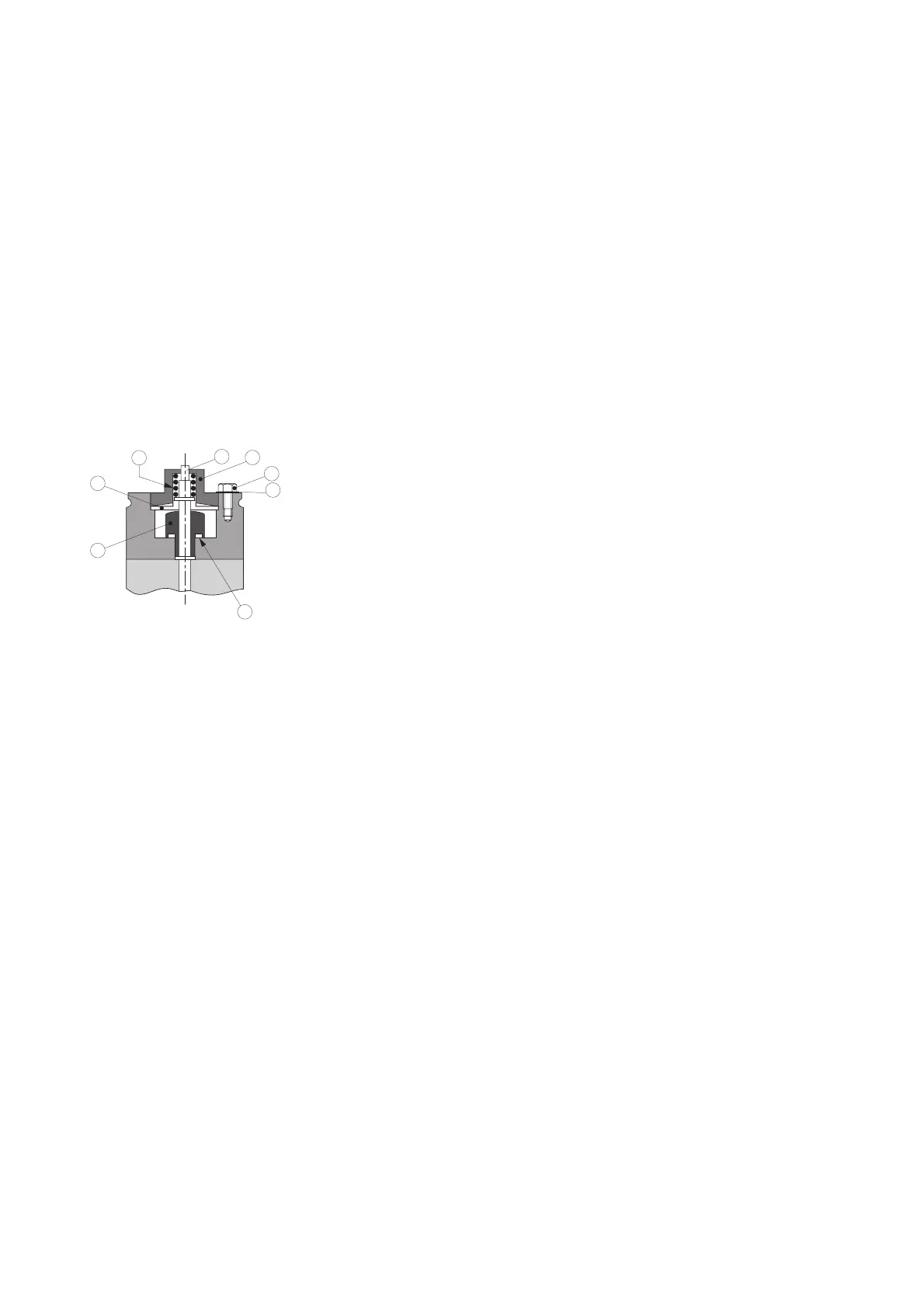
Disassembling the rear flange (4)
C1 model: Remove the 2 screws (32) and remove the case bushing (31).
Remove screws (21) then (18) and equipped body (11).
Remove screws (20) then (19) and cylinder (17), spring (16), piston (15) and diaphragm
(14).
Remove seat (13) and O-ring (12). Change the O-ring prior to reassemble.
Unscrew the oil inlet tube fixation (3) and (4) and remove the stop (5) (SD and C1
models). Remove the oil inlet tube (1).
Unscrew air inlet tube (7) and remove spring (6).
If necessary, note settting of air inlet tube (7): number of turns until tube stops moving
turning clokwise.
Remove vane (9).
Disassembling oil pump (11)
(see page N–6)
Removing HP rotor (9) and
HP stator (12)
Removing flange (21)
Removing LP rotor (26)
and LP stator (29)
Disassembling the
pumping module
(see page N-4)
Removing the exhaust valve
cover (16) and (32)
Remove the screws (18), (17) then (34), (33) and the cover(s) (16), (32).
Remove the exhaust valves (13), (30) and their springs (15) (31) and for 63C1 model,
the washer (14).
Insert two screwdrivers in the notches of the flange (21) and release the flange (21).
Remove the O-ring (24).
Remove tube (37) and O-ring (36).
Remove the HP rotor (9) by sliding it out of the HP stator (12).
Remove vanes (10) and their springs (39).
Insert two screwdrivers in the two notches of the HP stator (12) and twist to remove
plate off pins (19).
Remove HP stator (12) straight out.
Remove the O-ring (20).
SD Model Oil jet (23) lubricates the first stage. Do not remove it for cleaning.
When reassembling, spray with compresses air to remove any obstructions.
Remove the LP rotor (26) by sliding it out of the LP stator (29).
Remove vanes (27) and their springs (38).
Insert two screwdrivers in the two notches of the LP stator (29) and twist to remove
plate of pins (7) (N-2).
Remove LP stator
(29) straight out.
Remove the O-ring (35).
Remove tube (38) and O-ring (37) (N-2).
19
3
5
20
21
23
22
4
16
14
13
12
19
18
17
15
Disassembling the pump (cont’d)