EN – 52
Reassembling the pump
• All parts must be dry so that no solvent remains, particularly in blind holes
• Check that the lubrication holes are not blocked.
• Oil used for lubricate pump parts must be the same as oil used for pump operation.
Component
preparation
Before reassembly • Coat all pump parts and lips of shaft seals with clean oil. Make sure seals are
correctly installed (see page 50).
• Fill lubrication holes of bearings and seal seats with oil.
• Do not put too much oil in the bottoms of the holes for the plate/stator
alignments pins.
• Tighten nuts without forcing maximum torque (see chapter «Nomenclature»)
• Rest the frame (B) on a flat surface in order to assemble the pump verticaly.
The bushings in the frame and plates can be replaced, but special machining is
required whenever a bushing is changed. Consult service center for assistance.
Assembling moving
parts
(see page N-4)
• Be aware of the LP valve (27) (N-4) direction of assembly: their grooves must be
visible in a same side of view (see the picture).
• Reassemble moving parts in reverse order of disassembly.
• Before replacing valves, pour a little oil into the stators through the valve holes.
• Before reassembling oil pump (11) (N-6), assemble fan (17) (N-2): using a new self-
locking screw (19) (N-2) to tighten it (Maintenance kit page 44).
Installing bubbler (C2 Model)
(see page N-10)
Before tightening nuts (1) (N-4) to fasten rear flange (4) (N-4), replace bubbler as
follows:
• Put a PTFE tape on base (54) and gas connection threads.
• Set the pipe (55) in the central housing (1).
• Put a new seal (53) and the washer (52) on the upper end of the pipe and then
screw it in the base (54).
• Set the two tube fasteners on the studs and screw it in the two nuts (1) (N-4).
• Put a new seal on (51) and screw it on (50).
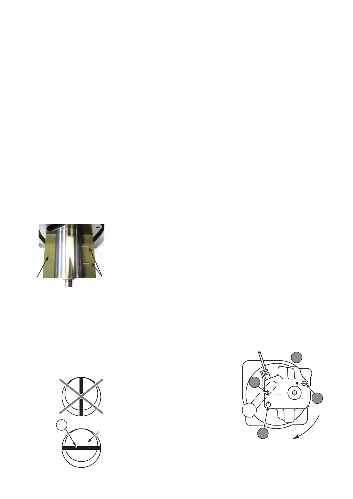
Assembling oil pump
(see page N-6)
9
Rotor
Mount all necessary parts on oil pump body
proceeding in reverse order as described page 46.
Place slot of oil pump rotor in horizontal position
(parallel to pump base).
Fan can be used to turn rotor, but never insert
a screwdriver in the rotor slot as this may
cause damage.
Place vane (9) in its slot.
With pump horizontal, let pump body (11) drop
by gravity on to rotor.
With pump vertical, turn pump body (11)
clockwise around alignment pin (8), to bring
it into contact with the rotor without forcing.
Never rest pump body on rotor; this will
eliminate bearing play.
Fit two screws (21) equipped with washer (18). They must be tightened first (21a), and
(21b) second (maximum torque: 10 Nm.)
11
21a
8
21b
1 groove
2 grooves