S-DRIVE - INSTALLATION PG DRIVES TECHNOLOGY
SK76745/10
3.7 Solenoid Brake Connection
The solenoid brake should be 24V and should not require more than 1.25A to operate. The S-Drive’s brake output has a
continuous rating of 1.25A. If the continuous current is greater than this level, then the controller may shut down the brake output
in order to protect it. If the solenoid brake current is less than 10mA, the controller will detect an open-circuit brake condition.
If the brake is manually disengaged in order to freewheel the scooter then a Brake Released Switch must be fitted and
connected as shown in the S-Drive Wiring Diagram in section 3.1.
This will result in the S-Drive preventing drive, detecting a freewheel situation and indicating this as a Solenoid Brake Trip. (Trip Type
9).
Due to the S-Drive’s ability to operate at low voltages, the Solenoid Brake(s) fitted must be capable of operating over the same
range.
It is the responsibilities of the scooter manufacturer to test the effectiveness of the Solenoid
Brake(s) over the entire operating range of the S-Drive.
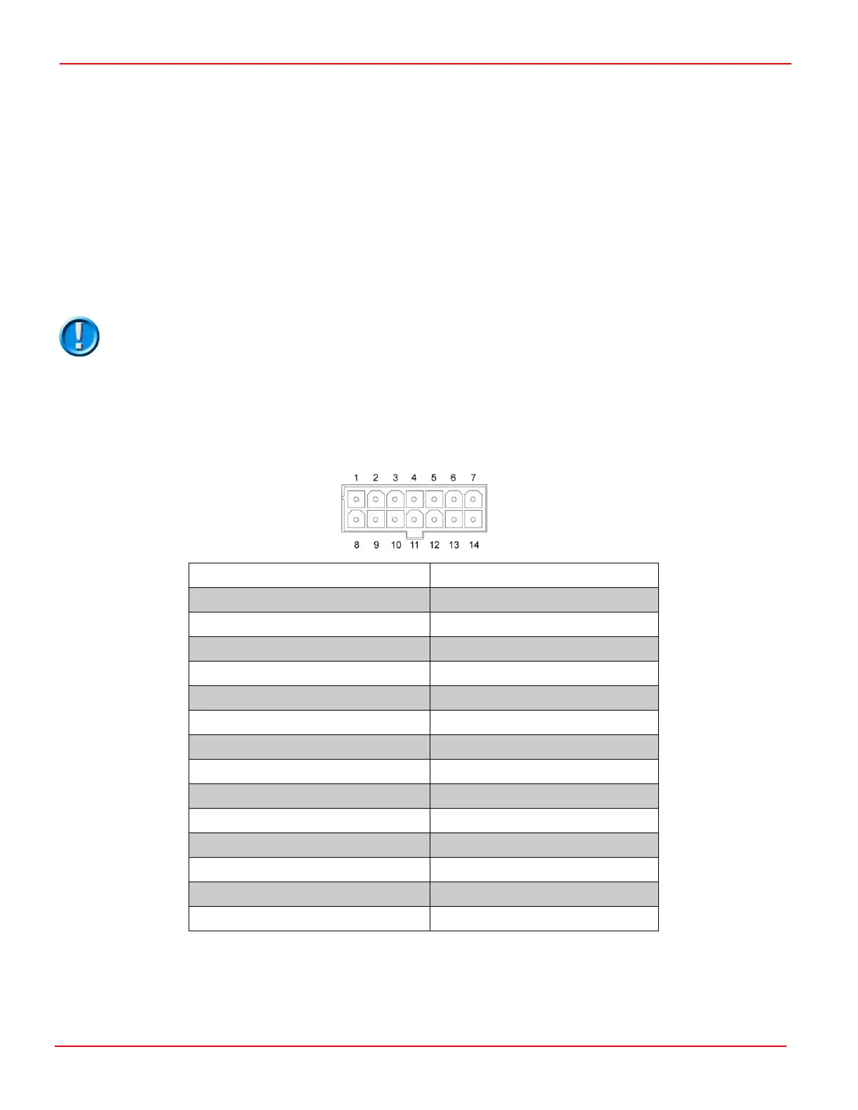
4 Tiller Interface
The Tiller Interface connections are via a 14 way Molex ‘Mini-Fit-Jr.’ connector. PGDT can supply these parts or Molex can be
contacted directly. Refer to section 3.2.3 for part numbers and connector details.
24V B+ (S200 fused 3.75A)
Speed Limiting Potentiometer
The S-Drive Scooter Controller is a versatile method of scooter control. To maximize this versatility the Tiller Interface can be wired
in many different ways to suit a range of scooter functionality. Each method of connection is individually described in this section.