S-DRIVE - INSTALLATION PG DRIVES TECHNOLOGY
SK76745/10
The parameter Speed Limit Pot. Enabled should be set to On.
To comply with ISO7176-14: 2008 section 7.2.3.4 PGDT recommends speed limiting potentiometers
be fitted in Parallel only.
4.3 ISO-Test Resistor Configuration
If a Speed Limit Pot. is fitted in parallel, or not fitted at all, then it is not necessary to fit an ISO-Test resistor in order to comply with
ISO7176-14:2008 section 7.2.3.4.
Fitting a Speed Limit Pot and ISO-Test Resistor in series does NOT comply with ISO7176-14:2008
section 7.2.3.4
To program the S-Drive to suit the scooter installation, Refer to Chapter 3.
4.4 On/Off Switch
Pin 5 is the battery positive supply to the controller from the on/off switch. The maximum power consumption of the controller via
this connection will not exceed 1A.
Large capacitances connected between pin 5 and 0V may affect the ability of the S-drive to switch on or off reliably. If it is
desired to connect a large capacitance, for example to damp a battery gauge voltmeter or to suppress a horn sounder, then
connection should be made between battery 24V (pin 7) and 0V.
It is the responsibility of the scooter manufacturer to test the effectiveness of the On/Off switch.
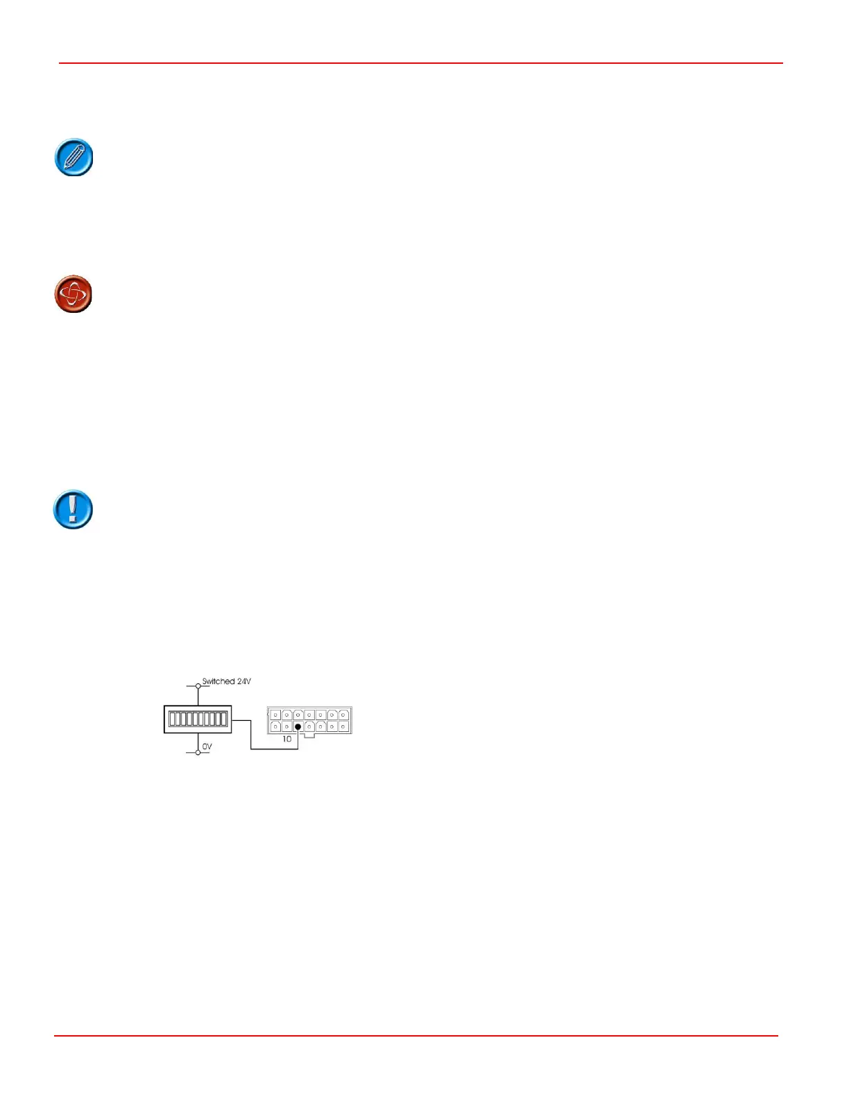
4.5 Status Indicator
This output controls either a PGDT TruCharge type status indicator or a single bulb (or LED) type Status Indicator.
If you are using a PGDT TruCharge indicator, the data connection must be to pin 10.
The maximum current rating of the output is 50mA, you must ensure that the indicator does not draw more current than this
value.
If you are using a bulb, the bulb can be connected directly between pin 10 and 0V (Highside) or pin 10 and switched 24V
(Lowside). The bulb must be 12V with a maximum rating of 600mW when connected Highside and 24V with a maximum rating of
600mW when connected Lowside.
If you are using an LED, it is connected between the same points but you must provide a series connected current limiting
resistor.