EMSinjection system
The injection system is of the integratedinjection and ignition type.
Injection is indirect in the manifold throughelectronic injector.
Injection and ignition are timed on the 4-strokecycle by a wheel speed sensor pivoted on the camshaft control and a
reluctancevariation sensor.
Carburetion and ignition are managed on thebasis of the engine rpm and the gas valve opening.?Further corrections
are made according to the followingparameters:
- Cooling fluid temperature
- Sucked air temperature
- Ambient pressure
The system implements an idle feeding correctionwith cold engine through a stepper motor on a by-pass circuit of the
gas valve.The controller manages the stepper motor and the injector opening time, therebyensuring the idle
steadiness and the proper carburetion.
In all working conditions, carburetion ismanaged by changing the injector opening time.
The fuel feeding pressure is kept constant basedon the ambient pressure.
The
feedingcircuit
consists of:
- Fuel pump
- Fuel filter
- Injector
- Pressure regulator
Pump, filter and regulator are placed into thefuel tank by a single support.
The injector is connected by two pipes providedwith quick couplings. This allows obtaining a continuous circulation,
therebyavoiding the risk of fuel boiling. The pressure regulator is located at the endof the circuit.
The fuel pump is controlled by the EMScontroller; this ensures the vehicle's safety.
The
ignitioncircuit
consists of:
- H.V. coil
- H.V. cable
- Screened cap
- EMS controller
- Spark plug
The EMS controller manages the ignition withoptimum advance, ensuring the timing on the 4-stroke cycle (ignition
onlyduring compression).
The EMS injection-ignition system manages theengine operation by a preset program.
Should any input signals fail, an acceptableworking order of the engine is ensured to allow the user to reach a
servicestation.
Of course, this cannot happen when therevolution-stroke signal is lacking, or when the failure concerns the control
circuits:
- Fuel pump
- H.V. coil
- Injector
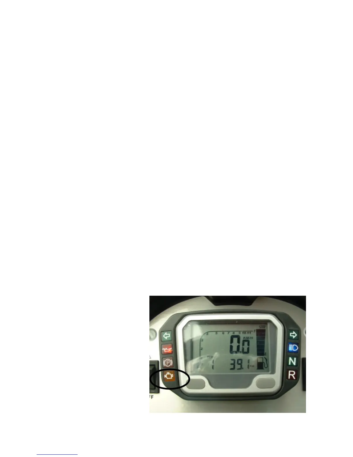
The controller is provided with
an auto-diagnosis system
connected to an indicator in the
instrument panel.
Failures are detected and
restored by the diagnostic tester
dwg. 020460Y.
In any case, when the fault has
been fixed the stored value is
automatically deleted after 16
usage cycles (cold start, running
in temperature, stop).
The diagnostic tester is also
PGO BR-500 ENGINE
P.9-3
Introduction



 To Next Page