Circuit layout
The electric fan system is powered by a remotecontrol switch connected under the panel and interlocked to the
injectioncontroller.
The injection controller manages the electricfan control according to the temperature detected on the engine.
In case of a prolonged activation of theelectric fan rotation, before checking the electric system perform thefollowing
checks:
- expansion tank level
- engine connection pipe bleeding
- head output bleeding
- thermostat efficiency
- pump efficiency
For these checks, see the "Cooling"chapter.
To check the circuit, proceed as follows:
TERMINALS
CONDITIONS
STANDARD
5 - 23
Switch set to "ON"
Switch to "RUN"
Side stand raised
Electric fan off
Battery voltage
1
CONTROLLER
4
KEY SWITCH
2
ELECTRIC FAN
5
ELECTRIC FAN REMOTE CONTROL
SWITCH
3
FUSE 30A
1
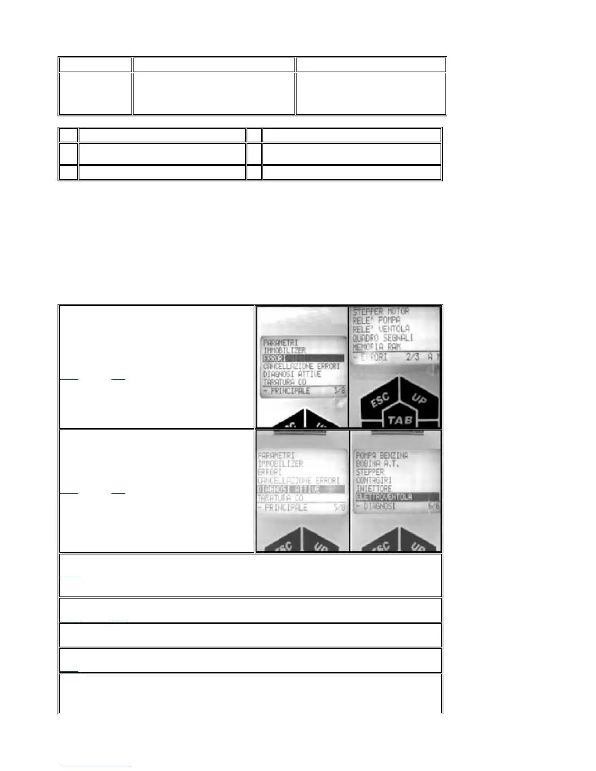
- Connect the diagnostic tester dwg. 020480.
Set the switch to "ON" with switch to "RUN"
and side stand raised. Select the "ERRORS"
function. Check whether the controller has
detected any failures relating to the electric fan
control circuit.
YESgo to 8 NOgo to 2
2
- Select the menu on the "ACTIVE
DIAGNOSIS" function. Start the electric fan
diagnosis function. Acoustically check the
electric fan rotation. Wait for the diagnostic
tester results.
YESgo to 3 NOgo to 4
3
- Test successful. The fan is rotating.
YESgo to 5
4
- Test failed. The fan is not rotating.
YESgo to 8 NOgo to 6
5
- The electric fan system is conforming.
6
- Test successful. The fan failed.
YESgo to 7
7
- The remote control switch circuit is efficient. Check the electric fan connection circuit, the
remote control switch contacts efficiency, the positive lines, the negative line and the electric
fan motor.
PGO BR-500 ENGINE
P.9-90
Electric Fan control circuit
 Loading...