Circuit layout Legal Notes
PGO BR-500 ENGINE
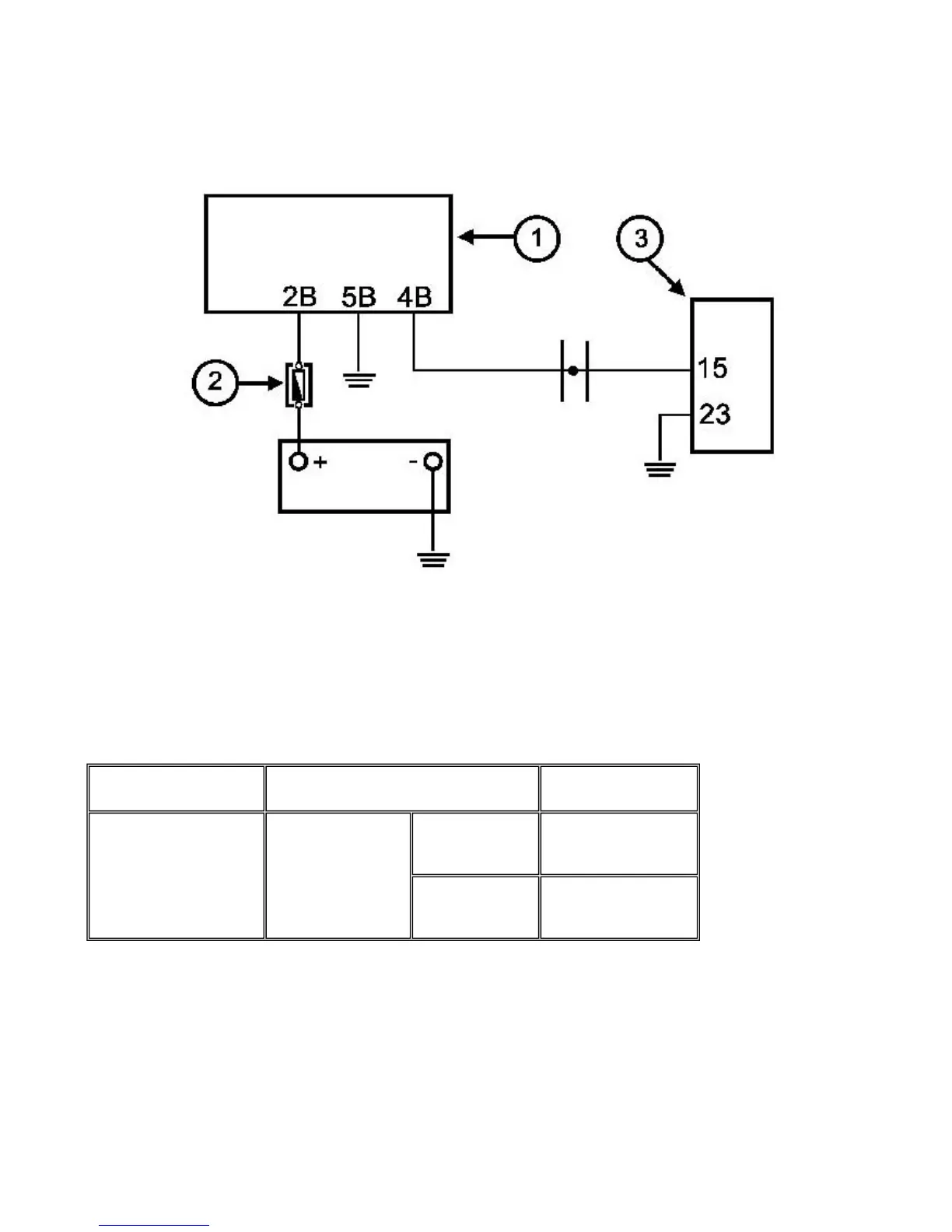
Circuitlayout1
INSTRUMENT UNIT
2
FUSE 7.5A
3
CONTROLLER
Theinjection indicator light is controlled upon every switching to "ON" bythe 3-second timing generated by the digital
instrument. This step is normallyinterrupted by the injection controller control. The timing lasts 5 seconds.
The diagnostic tester dwg. 020460Y is notprogrammed to check this circuit.
Proceed as follows:
TERMINAL
CONDITIONS
STANDARD
VALUES
15 - 23
- switch set to "ON"
- side stand raised
- switch to "RUN"
during the check O V
after the check battery voltage
P.9-34
Injection indicator circuit



 To Next Page