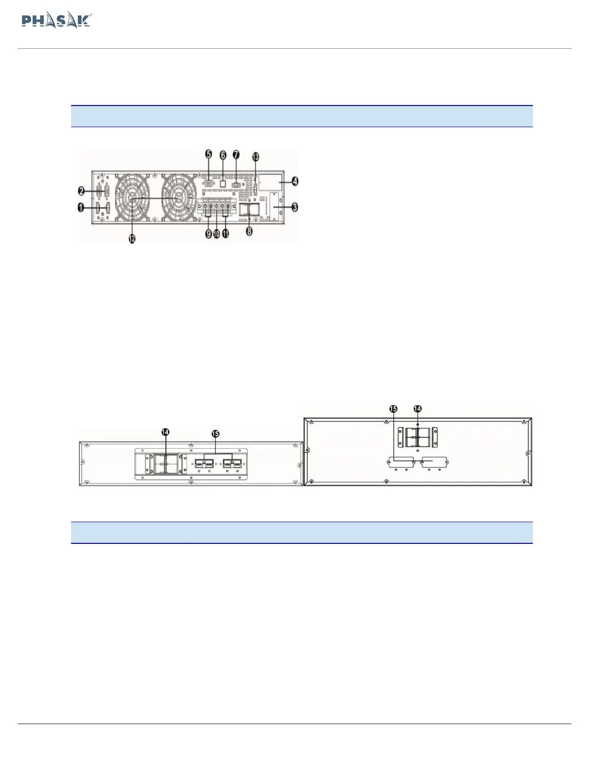
1. Share current port (only available for parallel
model) | 2. Parallel port (only available for parallel
model) | 3. External battery connector | 4. Intelligent
slot SNMP/Web-AS400 | 5. RS-232 communication
port | 6. USB communication port |
7. Emergency power off function connector (EPO
connector) | 8. Input circuit breaker |
9. Output terminals | 10. Ground |
11. Input terminals | 12. Cooling Fan |
13. External maintenance bypass switch port | 14.
Battery pack output circuit breaker | 15. External
battery connector |
6K Diagram Battery bank 2U 10K Diagram Battery bank 3U
2.2. Setup the UPS
Installation and wiring must be performed in accordance with the local electric
laws/regulations and execute the following instructions by professional personnel.
70 / 100