- 34 -
8.
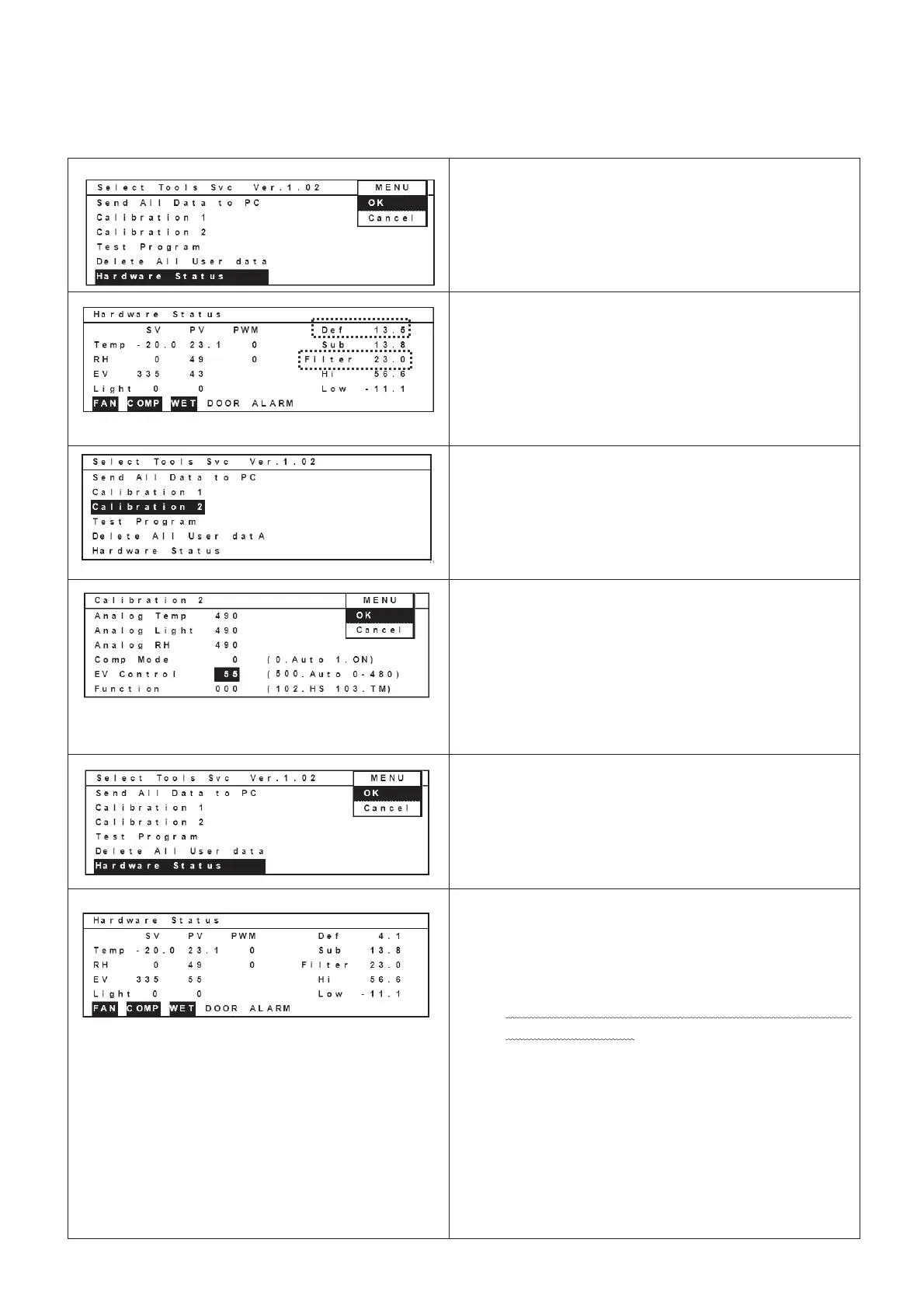
Move curser to “Hardware Status” column after
temperature is stabilized.
Select “OK” in the MENU bar and press ENTER
key to display Hardware Status screen.
9.
Write down values besides “Def” column and
“Filter” column.
Select “OK” in the MENU bar and press ENTER
key to display Hardware Status screen.
The left picture is the example which shows filter
and def temperatures
(Ex. Def: 13.5Υ Filter: 23.0Υ)
10. Move curser to display “Calibration 2” with reverse
video.
Press ENTER key to display Calibration 2 screen
11.
Refer to attached Table of corresponding values
between Def temperature display and Electric
valve offset”.
Ex) Add a value which is correspond to the table
to 43. (43 + 12 = 55)
Input 55 besides EV Control column.
Select OK in the MENU bar and press ENTER
key to display Select Tools Svc screen.
12.
Run the unit for 3hours to stabilize temperature.
(Variation: +/-1Υ)
Move curser to display Hardware Status with
reverse video.
Select OK in the MENU bar and press ENTER
key to display Hardware Status screen.
13. Ensure a value (Ex.”4.1”) besides “Def” column
should be in the range (Ex.3.2~5.2Υ) described in
the Table of corresponding values between Def
temperature display and Electric valve offset”.
If the value is out of the range, repeat the
procedure 11 to 13.
Refer to attached “Table of corresponding values
between Def temperature display and Electric
valve offset”.
Ex) Add a value which is correspond to the table to
a value which was input in the procedure 11.
(55 + 2 = 57) (Ex. Def: 5.5Υ Filter: 23.0Υ)
Input “57” besides “”EV Control” column.
Select “OK” in the MENU bar and press ENTER
key.
 Loading...