24 241P3 LCD
DDC Instructions
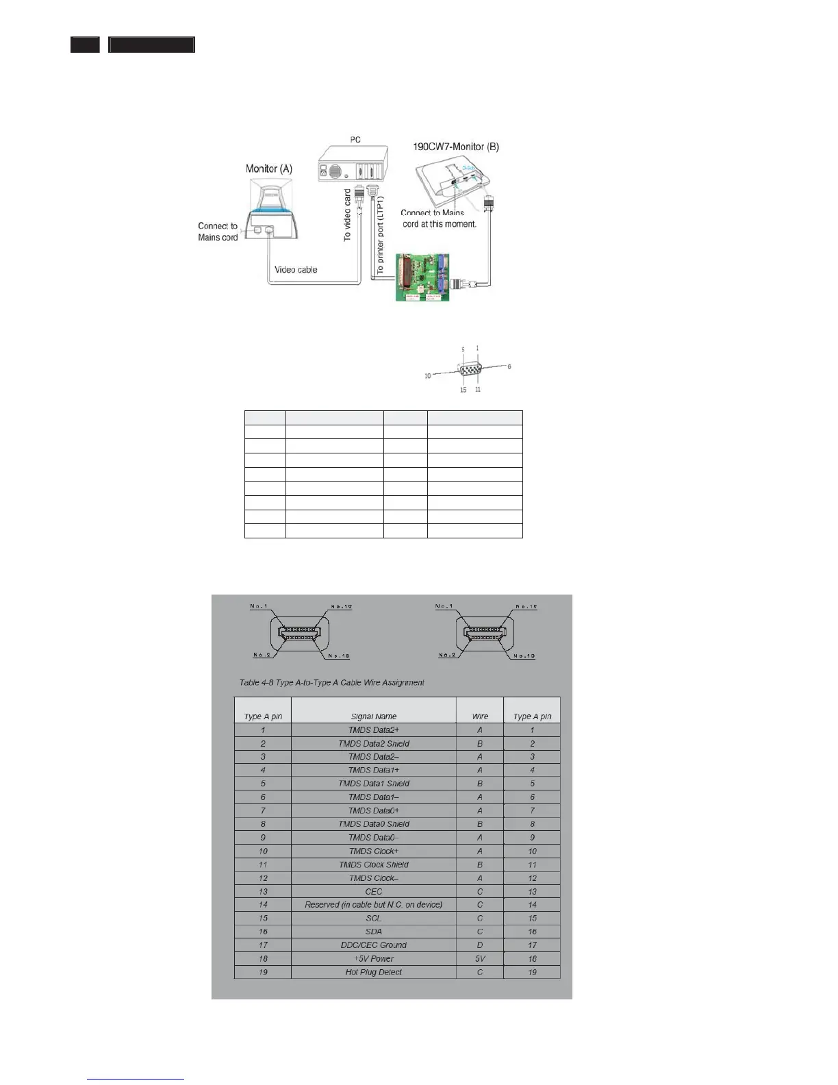
5. Connect and Mains cord to Monitor as shown in Fig.2.
Fig.2
Pin assignments :
A. 15-pin D-Sub Connector
B. Input HDMI Connector pin
PIN No. SIGNAL PIN No. SIGNAL
1 Red 9 DDC +3.3V or +5V
2 Green/ SOG 10 Logic GND
3 Blue 11 Sense (GND)
4 Sense (GND) 12 Bi-directional data
5 Cable Detect (GND) 13 H/H+V sync
6 Red GND 14 V-sync
7 Green GND 15 Data clock
8 Blue GND
ʳʳ