Mechanical Instructions
EN 13TPM7.1E LA 4.
2011-Aug-19
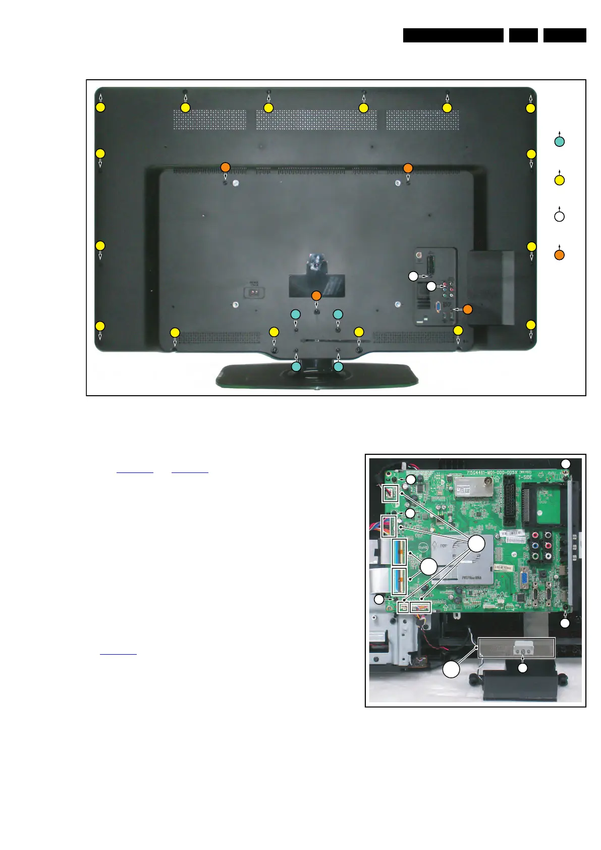
Figure 4-6 Rear cover removal 47"
4.3.2 Small Signal Board (SSB)
Refer to Figure 4-7
and Figure 4-8 for details.
Caution: it is mandatory to remount all different screws at their
original position during re-assembly. Failure to do so may result
in damaging the SSB.
1. Release the clips from both the LVDS Flat Foil connectors
that connect with the SSB [1].
Caution: be careful, as these are very fragile connectors!
Take the flat foils out of their connectors.
2. Release the clamps and unplug all other connectors [2].
3. Release the tape [3] near the bottom side of the set from
the LCD panel.
4. Remove the fixation screw from the clamp near the bottom
of the SSB, and take the clamp out [4].
5. Remove all other fixation screws from the SSB [5].
6. Take out the SSB together with its shielding.
7. Remove the screw near the L/R audio connectors [6].
8. The SSB can now be shifted from the side connector cover,
then lifted and taken out of the shielding [6]. Refer to
Figure 4-8
for details.
Figure 4-7 SSB removal [1/2]
19090_110_110505.eps
110505
1
M4 × 10
4
M3 × 8
3
2 × 11
3 × 24
2
1
1
1
1
2
2
2
2
3
4
2
2
2
2
2
2
2
2
2
2
2
2
4
4
3
4
19090_105_110414.eps
110505
5
5
5
5
1
3
6
2
4