Circuit Descriptions, Abbreviation List, and IC Data Sheets
EN 173BJ3.1E LA 9.
9.2 Power Supply
9.2.1 DC/DC converters
For a (more) detailed description of the on-board DC/DC
converters of the SSB see the BP2.xU Service Manual.
9.2.2 PSU’s
For a (more) detailed description of the used LCD Power
Supply Units see e.g. the BJ3.0x and FJ3.0x manuals.
9.3 Front-End
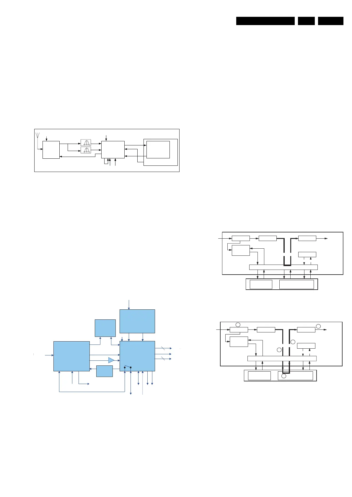
Figure 9-3 Block diagram analogue front-end
Main goal of the front-end module is to connect the host (core
with source processing) with the outside world via an RF
connector. For an analogue application the connection to the
outside world is through analogue broadcasts via terrestrial
connection. The analogue sets that use this chassis use the
UDA1318 as tuner, which delivers the analogue front-end as
depicted in figure “Block diagram analogue front-end”.
For a DVB-T application the connection to the outside world is
through DVB broadcasts via terrestrial connection. It delivers a
number of digital broadcasts services, grouped into a
frequency spectrum. The front-end module processes one
channel and forwards the digital channel to the core as MPEG
data packets at the demodulator’s output. To maintain common
naming with an ATSC application this path is also referred to as
the ‘in-band’ signal path.
Figure 9-4 Block diagram DVB-T front-end
9.4 Common Interface (CI)
9.4.1 Introduction
The digital sets of this chassis are provided with a special slot
(Common Interface - CI). Together with a Conditional Access
Module (CAM) and a smart card it is possible to receive
scrambled TV programs. This means that it is not necessary to
have a separate Set Top Box to receive digital cable SDTV and
HDTV programs (however this is still possible).
The removable smart card, distributed by cable companies,
allows you to tune digital and high definition scrambled or
encrypted cable channels through the cable antenna. The
smart card is also required to receive premium digital TV
channels and services (where available) through the cable. A
smart card functionality includes conditional access and copy
protection.
9.4.2 Implementation
1. The receiver receives the digital data stream.
2. The data flows into the Conditional Access Module, which
contains the content provider's unscrambling algorithms.
3. This module verifies the existence of a smart card that
contains the subscriber's authorization code.
4. If the authorization code is accepted, the CAM
unscrambles the data and returns the data to the receiver
(if the code is not accepted, the data remains scrambled,
restricting access).
5. The receiver then decodes the data and outputs it for
viewing.
Figure 9-5 In Band channel reception (without CAM inserted)
Figure 9-6 In Band channel reception (with smart card inserted)
MAIN
TUNER
ANALOG ONLY
MAIN-MPIF
IF FILTERING
ANTENNA
AVIP 1
(MAIN)
I2D-datalinks 1-2-3 **
CLK 13.5MHz
I2C on MMbus1,
@C0
I2C DMAbus
@9E
AGC1
Broadband
IF output
VIDEO-IF
SOUND-IF
V I D E O
A U D I O
C V B S
SAW
SAW
PNX2015
HV-PRM-MAIN
(HV Sync)
G_15970_052.eps
080307
G_15960_
Channel Decoder
TDA10046AHT
Channel Decoder
TDA10046AHT
F in
-
858 MHz
Main tuner
TD1316AF -3
Main MPIF
analog demodulation
I2C local
(addr 0xC0)
RF AGC monitoring
diff. IF @ 36.16 MHz
I2C DMA
(addr 0x14)
4MHz clock
IF AGC control
Power supply
control circuit
3V3
1V8 stab 3V3 delayed
DSM RC-filter
+ ADC
comparator
5V
stab
JTAG CI
control
TS co
TS CL
TS dat
8
2
reset
DSM
RC-filter
5V5V
TUNER
RF
7P03
STV0701
DEMOD
FRONT-END VIPER
OOB
PROCESSOR
CAS
PROCESSOR
POD MODULE
HOST-POD INTERFACE CONTROLLER CHIP
DEMUX
A/V
DECODER
CPU
QPSK
DEMOD
RX
QPSK
SYMBOLS
BYPASS
EMM
MESSAGES
MPEG
(SCRAMBLED)
MPEG
(DESCRAMBLED)
COMMANDS
F_15400_073.ep
13050
FAT
FDC
TUNER
RF
7P03
STV0701
DEMOD
FRONT-END VIPER
OOB
PROCESSOR
CAS
PROCESSOR
POD MODULE
DEMUX
A/V
DECODER
CPU
QPSK
DEMOD
QPSK
SYMBOLS
RX
BYPASS
EMM
MESSAGES
MPEG
(SCRAMBLED)
MPEG
(DESCRAMBLED)
COMMANDS
F_15400_074.eps
300505
HOST-POD INTERFACE CONTROLLER CHIP
FAT
FDC
1
2
4
3
5




 To Next Page