Service Modes, Error Codes, and Fault Finding
EN 34 BJ3.1E LA5.
5.5 Error Codes
5.5.1 Introduction
The error code buffer contains all detected errors since the last
time the buffer was erased. The buffer is written from left to
right, new errors are logged at the left side, and all other errors
shift one position to the right.
When an error occurs, it is added to the list of errors, provided
the list is not full. When an error occurs and the error buffer is
full, then the new error is not added, and the error buffer stays
intact (history is maintained), except when the error is a
protection error.
To prevent that an occasional error stays in the list forever, the
error is removed from the list after more than 50 hrs. of
operation.
When multiple errors occur (errors occurred within a short time
span), there is a high probability that there is some relation
between them.
Basically there are three kinds of errors:
• Errors detected by the Stand-by Processor. These
errors will always lead to protection and an automatic start
of the blinking LED for the concerned error (see paragraph
“The Blinking LED Procedure”). In these cases SDM can
be used to start up (see chapter “Stepwise Start-up”). Note
that it can take up to 90 seconds before the TV goes to
protection and starts blinking the error (e.g. error 53)
• Errors detected by VIPER that lead to protection. In this
case the TV will go to protection and the front LED should
also blink the concerned error. Depending on the software
version it is possible that this mechanism does not work.
See also paragraph “Error Codes” -> “Error Buffer” ->
“Extra Info”.
• Errors detected by VIPER that do not lead to
protection. In this case the error will be logged into the
error buffer and can be read out via ComPair, via blinking
LED method, or in case you have picture, via SAM.
5.5.2 How to Read the Error Buffer
Use one of the following methods:
• On screen via the SAM (only if you have a picture). E.g.:
– 00 00 00 00 00: No errors detected
– 06 00 00 00 00: Error code 6 is the last and only
detected error
– 09 06 00 00 00: Error code 6 was first detected and
error code 9 is the last detected error
• Via the blinking LED procedure (when you have no
picture). See next paragraph.
•Via ComPair.
5.5.3 How to Clear the Error Buffer
Use one of the following methods:
• By activation of the “RESET ERROR BUFFER” command
in the SAM menu.
• With a normal RC, key in sequence “MUTE” followed by
“062599” and “OK”.
• If the content of the error buffer has not changed for 50+
hours, it resets automatically.
5.5.4 Error Buffer
In case of non-intermittent faults, clear the error buffer before
you begin the repair (before clearing the buffer, write down the
content, as this history can give you significant information).
This to ensure that old error codes are no longer present.
If possible, check the entire contents of the error buffer. In
some situations, an error code is only the result of another error
code and not the actual cause (e.g., a fault in the protection
detection circuitry can also lead to a protection).
There are several mechanisms of error detection:
• Via error bits in the status registers of ICs.
• Via polling on I/O pins going to the stand-by processor.
• Via sensing of analogue values on the stand-by processor
or the Viper.
• Via a “not acknowledge” of an I
2
C communication.
Take notice that some errors need more than 90 seconds
before they start blinking. So in case of problems, wait 2
minutes from start-up onwards, and then check if the front LED
is blinking.
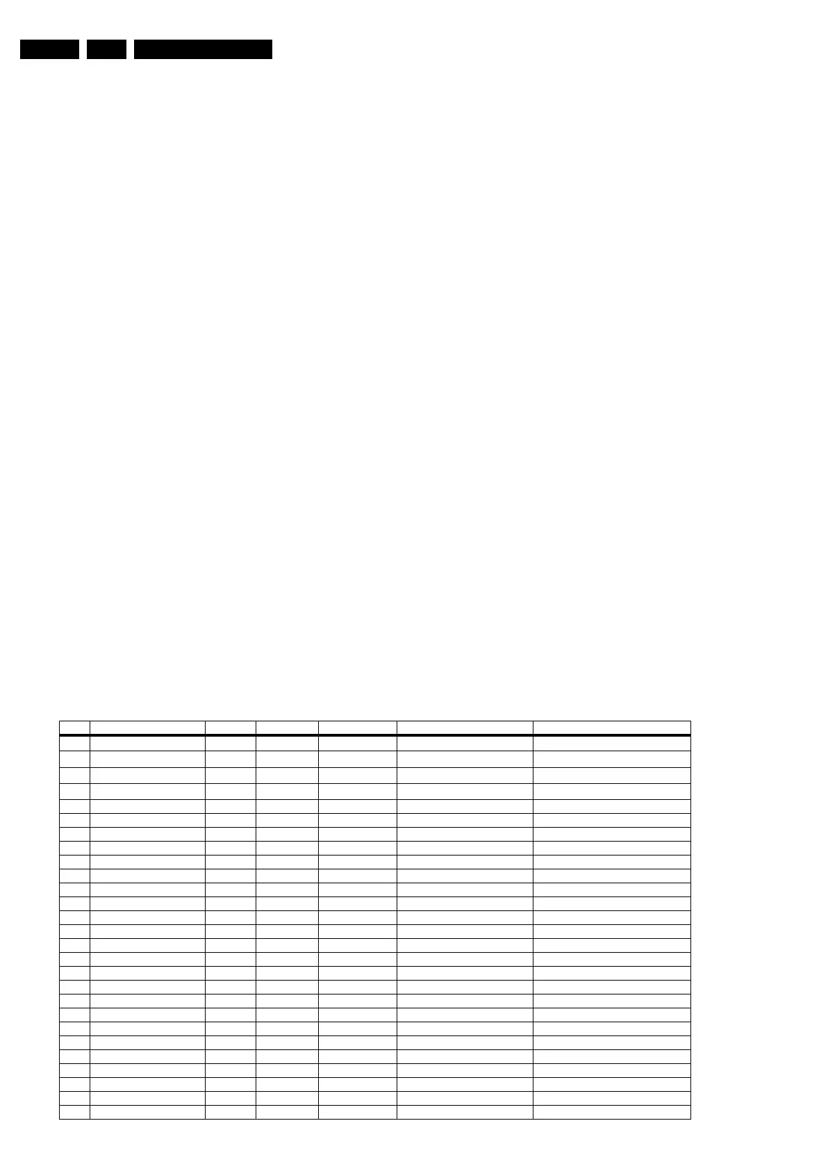
Table 5-3 Error code overview
Error Description Error/Prot Detected by Device Defective module Result
1
I
2
C1
P/E VIPER /
I
2
C1_blocked
Protection + Error blinking / Error logged
2
I
2
C2
E VIPER /
I
2
C2_blocked
Error logged
3
I
2
C3
P Stby µP / / Protection + Error blinking
4
I
2
C4
E VIPER /
I
2
C4_blocked
Error logged
5 VIPER does not boot P Stby µP PNX8550 / Protection + Error blinking
6 5V supply P Stby µP / / Protection + Error blinking
7 8V6 supply P Stby µP / / Protection + Error blinking
8 1.2V DC/DC P Stby µP / / Protection + Error blinking
11 3.3V DC/DC P Stby µP / / Protection + Error blinking
12 12V supply P Stby µP / / Protection + Error blinking
14 Audio P Stby µP / / Protection + Error blinking
18 MPIF1 ref. freq. E VIPER PNX3000 IF I/O Error logged
25 Supply fault P Stby µP n.a. / Protection + Error blinking
27 PNX2015 HD subsystem part E VIPER / / see extra info
29 AVIP 1 E VIPER / / see extra info
31 AVIP 2 E VIPER / / see extra info
32 MPIF1 E VIPER PNX3000 analogue 1 front end 1 Error logged
34 Tuner1 E VIPER / Tuner 1 Error logged
36 OFDM (channel decoder) E VIPER TDA10046 / Error logged
39 POD/Common Interface E VIPER STV0701 / Error logged
43 Hi Rate Front End E VIPER TDA9975 HDMI Error logged
44 NVM P Stby µP / / see extra info
45 Columbus 1 E VIPER PNX2015 Comb filter Error logged
46 Pacific 3 E VIPER / / TV to standby + Error logged
53 VIPER P Stby µP PNX8550 / Protection + Error blinking
63 Power OK P VIPER / / Protection + Error blinking (see extra info)
64 Display E VIPER / / Error logged