9 APPENDIX
9.1 Pin Configuration
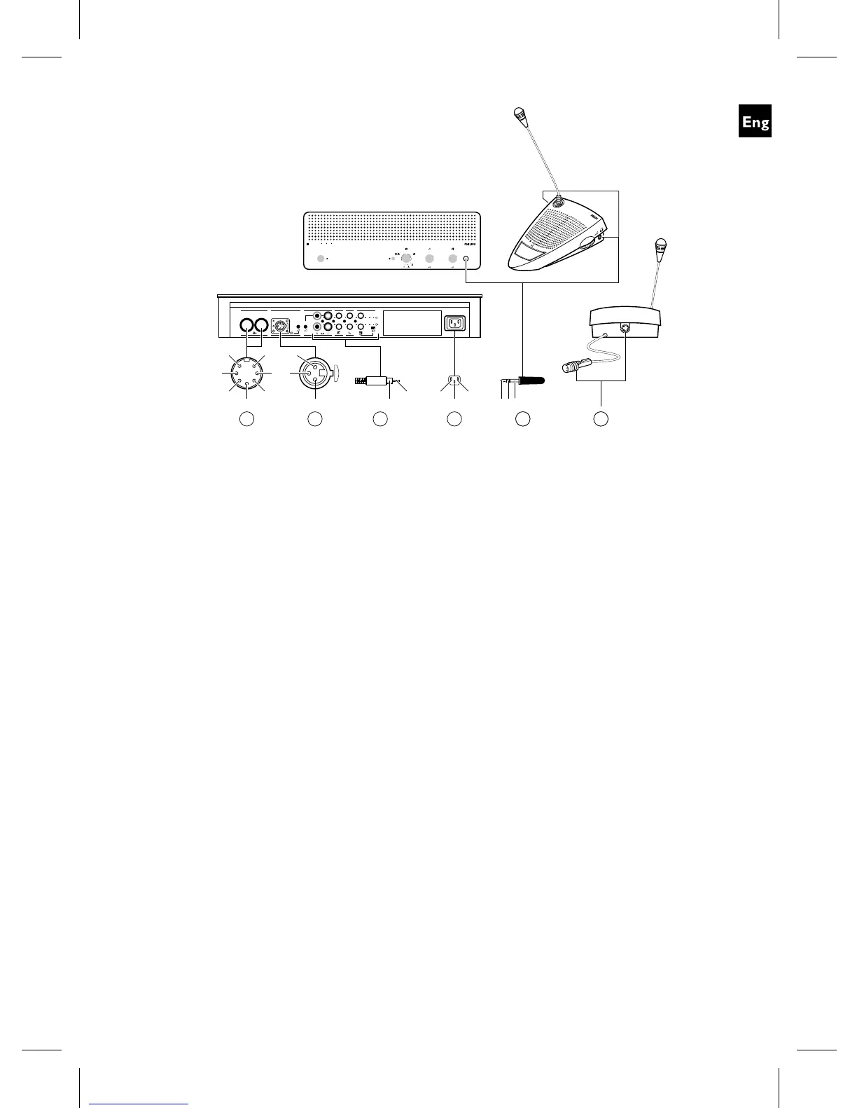
9.1.1 Trunk Connections (A)
1 Audio contribution line
2 GND
3 Audio distribution line
4 Control line 1
5 Control line 2
6 V+ supply
7V−supply
9.1.2 External Microphone (XLR)
(B)
1 GND (0V, phantom supply)
2 Signal + (+12V, phantom supply)
3 Signal − (+12V, phantom supply)
phantom supply acc. to
DIN45596
9.1.3 CINCH Connector (C)
1 Signal +
2 Screen
9.1.4 Mains Connector (D)
1 Mains
2 Earth
3 Mains
9.1.5 Headphone Jack-plug
(3.5mm) (E)
1 Tip - Signal +
2 Ring - Signal −
3 Sleeve - Electrical earth/screen
CCS
800
0
1
2
3
4
5
6
7
8
9
10
0
1
2
3
4
5
6
7
8
9
10
4
3
2
1
1
2
3
4
GainGain
90-260 V~
Trunk in/out Recorder Line Telephone InsertionMicrophone
In
Out
6
1
4
2
5
3
1
3
72
3
2
1
A DBC
1
2
3
21
EA
Fig. 3
19