9 ANEXO
9.1 Configuración de las Clavijas
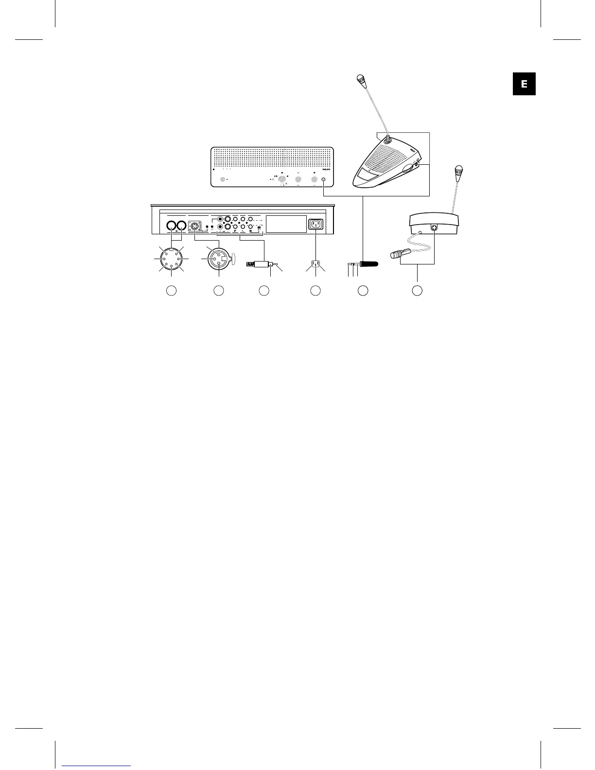
9.1.1 Conexiones Principales (A)
1 Línea de contribución de audio
2 Tierra
3 Línea de distribución de audio
4 Línea de control 1
5 Línea de control 2
6 Toma V+
7 Toma V-
9.1.2 Micrófono Externo (XLR) (B)
1 Tierra (0V, alimentación fantasma)
2 Señal + (+12V, alimentación
fantasma)
3 Señal - (+12V, alimentación
fantasma) alimentación
fantasma según DIN45596
9.1.3 Conector CINCH (C)
1 Señal +
2 Pantalla
9.1.4 Conector de Toma de
Corriente (D)
1 Toma
2 Tierra
3 Toma
9.1.5 Jack de los Auriculares (3.5
mm) (E)
1 Punta - Señal +
2 Anillo - Señal -
3 Capucha - Eléctrica tierra/pantalla
CCS
800
0
1
2
3
4
5
6
7
8
9
10
0
1
2
3
4
5
6
7
8
9
10
4
3
2
1
1
2
3
4
GainGain
90-260 V~
Trunk in/out Recorder Line Telephone InsertionMicrophone
In
Out
6
1
4
2
5
3
1
3
72
3
2
1
A DBC
1
2
3
21
EA
Fig. 3
89