BU RF Solutions
- 18 -
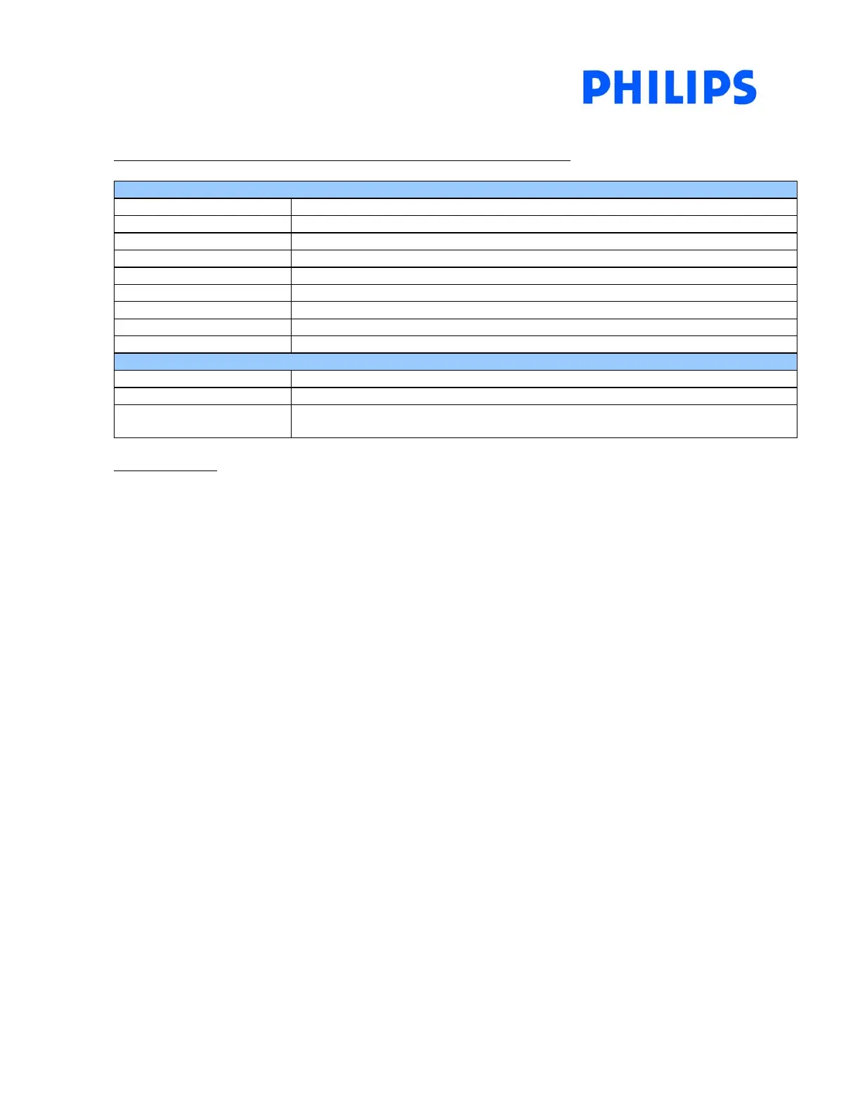
Table 5.3 Descriptions for the TDA10046 main user interface window
Channel Configuration
RF in [MHz] Set the RF input signal frequency in MHz
Bandwidth [MHz] Set the BW for the channel decoder in MHz
Modulation Set the modulation format (QPSK, 16QAM, 64QAM)
Spectral inversion Automatic search for spectral inversion or force the spectal inversion
Guard Interval Set guard Interval (Auto, 1/32, 1/16, 1/8, 1/4)
FFT size Set FFT size (Auto, 2K, 8K)
Channel Set Channel (HP, LP)
VR HP/LP Set code rate (1/2, 2/3, ¾, 5/6, 7/8)
Program Fron-End Run the algorithms to lock the complete system
Channel Status
AFC=xxKHz Indication of the corrected frequency drift in KHz
BER BER indication after the demodulation (RS decoder input)
RF AGC / IF AGC Value between 0 and 255 indicating the tuner AGC level. 0 = to much power/ 255 =
not enough power
LEDs indicators
• Tuner Lock
Indicator will turn green when tuner has been successfully locked to a wanted frequency.
• Frequency Lock
Indicator will turn green when the channel decoder has detected a COFDM signal.
• Time Lock
Indicator will turn green when the time recovery algorithm of the TDA10046 gets synchronized.
• TPS Lock
Indicator will turn green to indicate a good decoding of the TPS CRC stream.
• Frontend Lock
Indicator will turn green when IIC Communication has been established with the channel decoder.
• Uncorrected Blocks
Indicator will turn green when there are no uncorrected data blocks received by decoder.