BU RF Solutions
- 4 -
Introduction
This application note describes the use of our common CU/TU1216 NIM (Network Interface Module) evaluation
board that include both the hardware and software requirements.
A general block diagram and description will be provided for better product understanding.
1. General Block Diagram and Descriptions
In general, the CU1216 and TU1216 family is a single conversion full band Network Interface Module (NIM) with
a built- in PLL tuner and a Single Chip DVB-C and DVB-T Channel Decoder respectively.
For details of the model types, please refer to the respective datasheets. This test board can support all models as
mentioned.
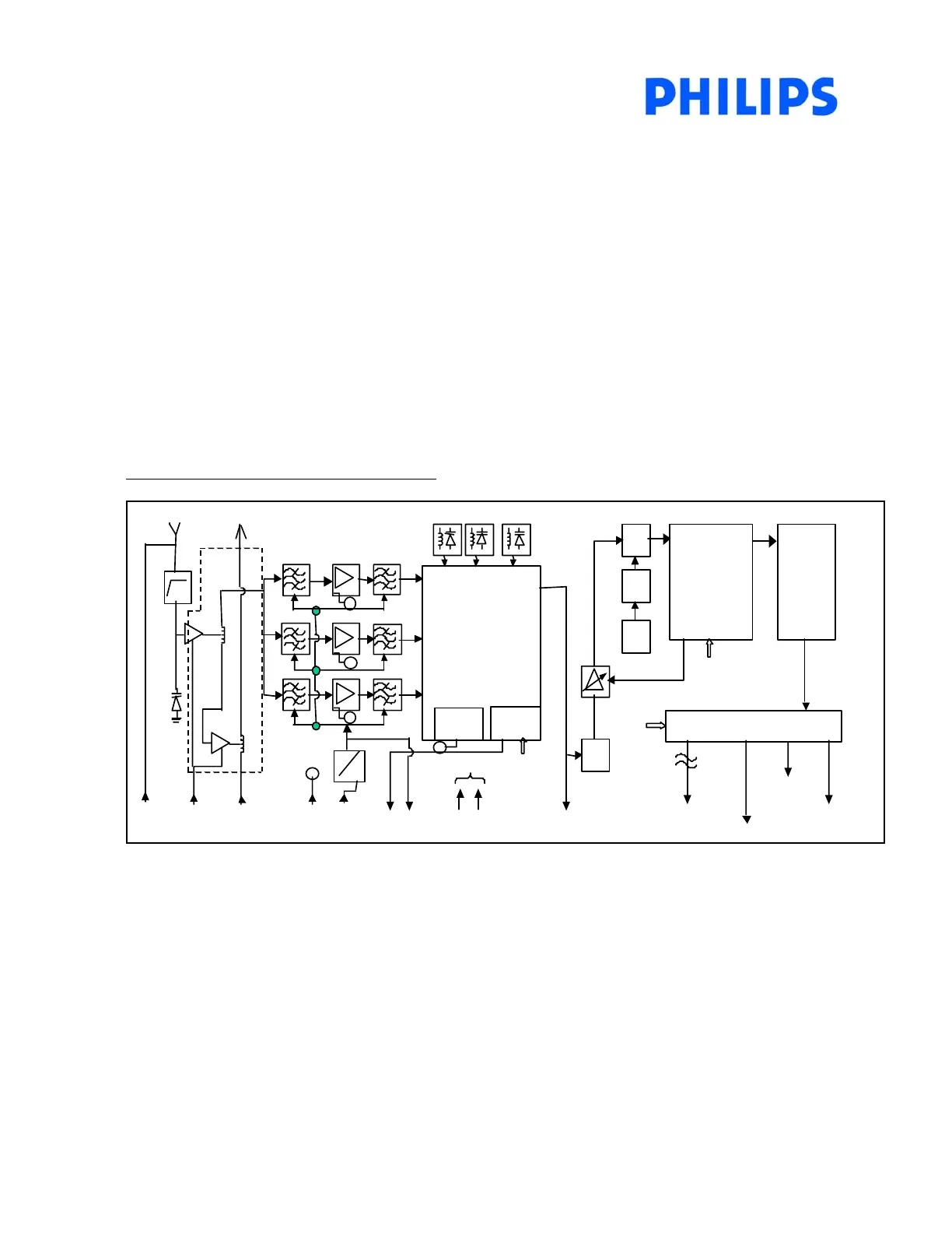
Figure 1.1 : CU1216 general block diagram
Oscillators
I
2
5V
I
2
Detector
RF AGC
xtal
PLL
DC
I
2
Core
I
2
C BUS
IF AGC
PLL
C BUS
IF
MOPLL I
SD ASCL
C BUS
GC
MP EG (D
... .D7 / SER)
MP EG_ T S_ CL K
MP EG_ D ATA_ VAL
MP EG_ PK T_S YNC
SAW
Output Formatter
C BUS
Demodulation
Error
Recovery
S
33V
+5V
GC
Vt
+5V(LT)
RF input
RF Mod in
RF out
nt_5 V
Ac tiv e
Loopthrough
The module consists of the following key features :
1. Loopthrough / RF Modulator input function – Passive loopthrough (LS), Active loopthrough (L) and Active
loopthrough/RF Mod input (LM) versions are available.
2. Tuner – high performance single conversion tuner that covers a frequency range from 51Mhz to 858Mhz.
33V tuning supply is derived from the single 5V supply by means of a DC/DC converter.
3. IF – Provides wideband IF output 36.15Mhz for analog reception. The narrowband IF output after SAW
filtering is being amplified further by a variable IF amplifier. This is controlled by the digital demodulator in
order to maintain a 2Vp-p differential amplified IF output to the DVB-C Receiver.
4. Digital Demodulator -- TDA10021 is used which can support up to 256QAM. The output can be either a
parallel or a serial MPEG-2 transport stream.