Mechanical Instructions
EN 10 DVDR615/694.
4.1.3 MOBO Board
– Remove the Front Panel assembly as given in 4.1.1
– Remove 6 screws 246 and 254
– Remove 4 screws 270
– Service position is achieved by flipping the MOBO board
above the Basic Engine
Figure 4-5
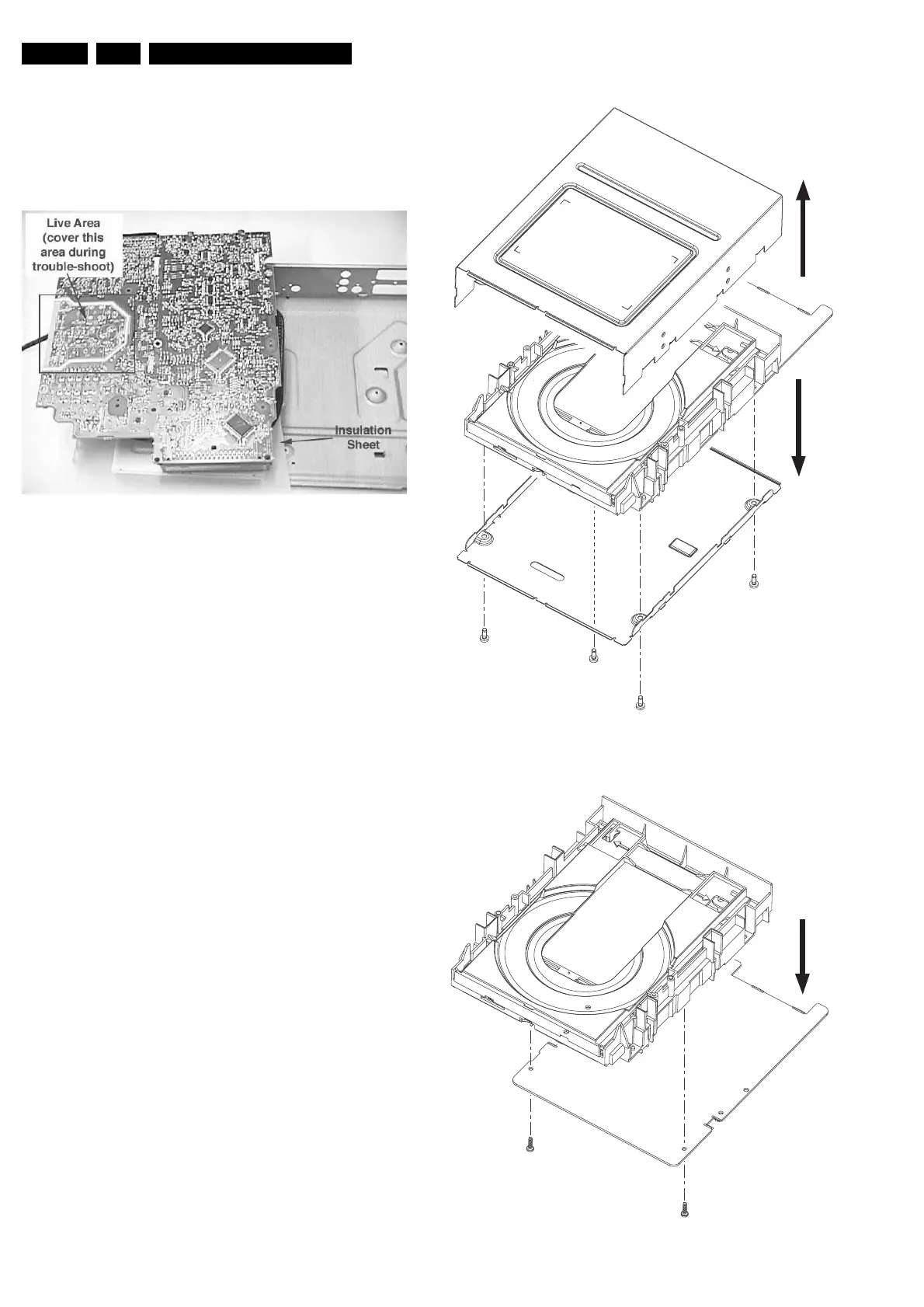
4.2 Dismantling and assembly of the VAU8041
Module
4.2.1 General
Follow the dismantling instructions in described order.
Do not place the unit with its PCB on a hard surface (e.g. table),
as it could damage the components on it.
Always place something soft (a towel or foam cushion) under it.
Never touch the lens of the OPU.
Take sufficient ESD measures during handling.
4.2.2 Dismantling the FEBE Board
– Remove 4 screws to remove the metal case 150+180
– Remove 2 screws to separate the FEBE board 179 from
the main Loader/Drive assembly
Note: After exchange of the PCB (or the Drive mechanism)
the complete VAU8041 has to be adjusted! Refer to
chapter 8 for adjustment instructions!
Figure 4-6 VAU8041 Module dismantling
Figure 4-7 Remove FEBE board
1
1
2
1
1
2
2
1
1
http://www.jdwxzlw.com/?fromuser=华盛维修