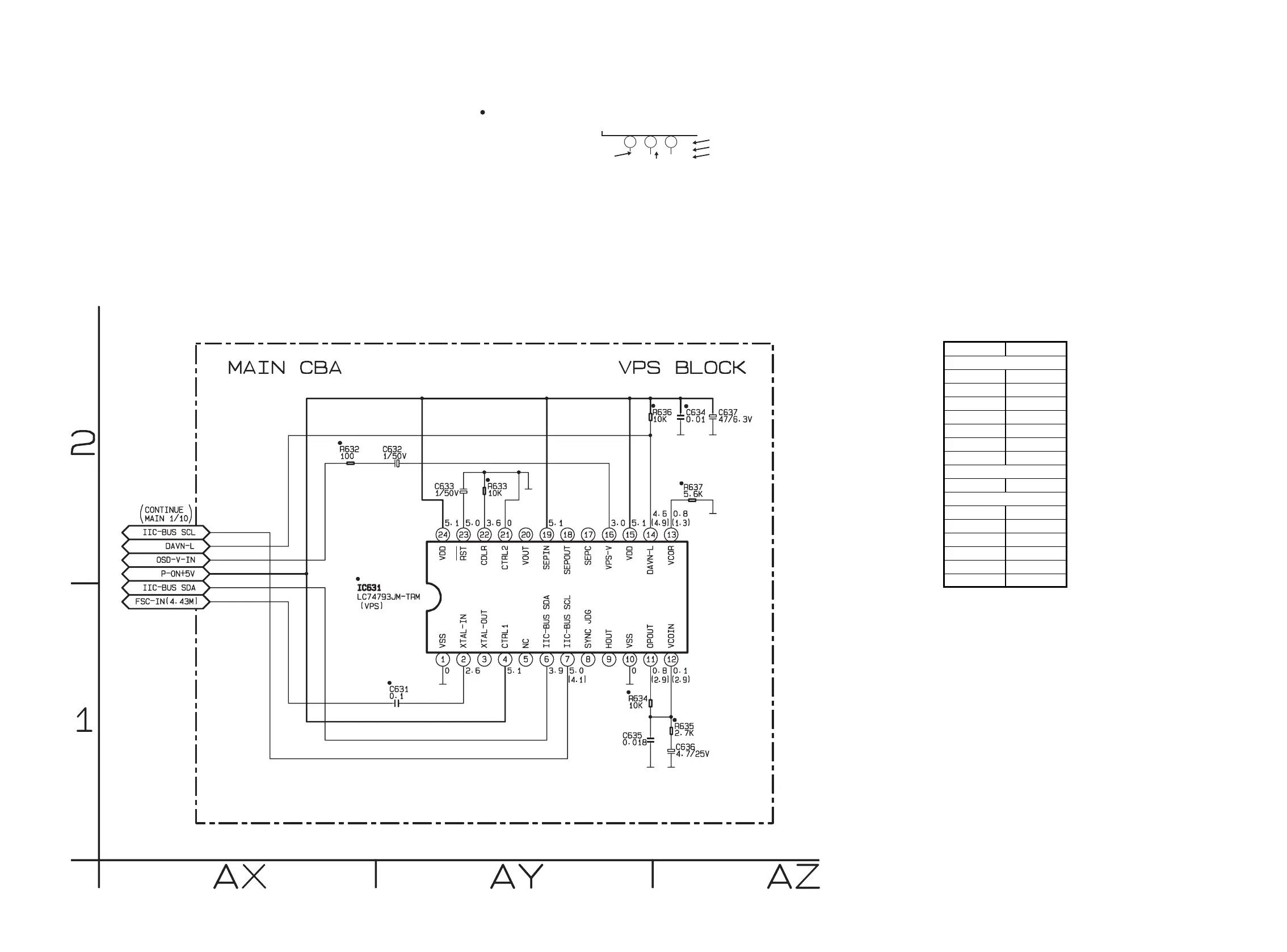
Main 10/10 Schematic Diagram < VCR Section >
1-12-25 1-12-26 H9720SCM10
“ “ = SMD
Voltage indications for PLAY, REC and DVD modes
on the Schematic Diagrams are as shown below:
1 2 3
5.0
(2.5)
<
0
>
~
5.0
THE SAME VOLTAGE FOR
PLAY,REC & DVD MODES.
INDICATES THAT THE VOLTAGE
IS NOT CONSISTENT HERE.
PLAY MODE
REC MODE
DVD MODE
MAIN10/10 Schematic Diagram
Parts Location Guide
Ref No. Position
C631 AY-1
C632 AY-2
C633 AY-2
C634 AZ-2
C635 AY-1
C636 AZ-1
C637 AZ-2
IC631 AY-1
R632 AX-2
R633 AY-2
R634 AY-1
R635 AZ-1
R636 AY-2
R637
AZ-2
IC
RESISTORS
CAPACITORS
www.freeservicemanuals.info