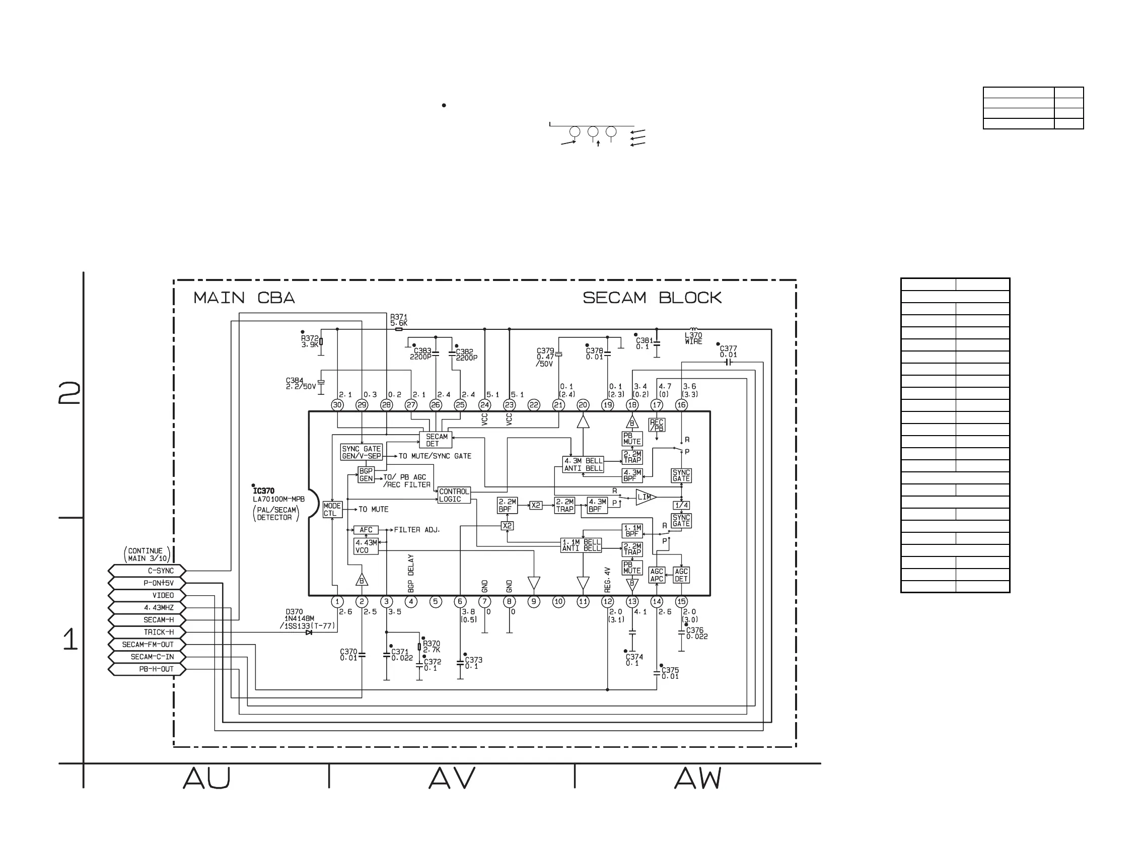
Main 9/10 Schematic Diagram ( C ) < VCR Section >
1-12-23 1-12-24 H9720SCM9
“ “ = SMD
Voltage indications for PLAY, REC and DVD modes
on the Schematic Diagrams are as shown below:
1 2 3
5.0
(2.5)
<
0
>
~
5.0
THE SAME VOLTAGE FOR
PLAY,REC & DVD MODES.
INDICATES THAT THE VOLTAGE
IS NOT CONSISTENT HERE.
PLAY MODE
REC MODE
DVD MODE
Comparison Chart of
Models and Marks
MODEL MARK
DVP620VR/00 A
DVP620VR/05 B
DVP620VR/02 C
MAIN9/10 Schematic Diagram
Parts Location Guide
Ref No. Position
C370 AV-1
C371 AV-1
C372 AV-1
C373 AV-1
C374 AW-1
C375 AW-1
C376 AW-1
C377 AW-2
C378 AW-2
C379 AV-2
C381 AW-2
C382 AV-2
C383 AV-2
C384 AU-2
D370
AU-1
IC370 AU-2
L370 AW-2
R370 AV-1
R371 AV-2
R372
AU-2
CAPACITORS
DIODE
COIL
RESISTORS
IC
www.freeservicemanuals.info