Circuit Descriptions, Abbreviation List, and IC Data Sheets
EN 116 EM5.1E9.
Signal IF-TER from the tuner is fed to pin 1 and 2, IF circuits of
TDA8887H IC7301 via SAW filter 1352. The AGC voltage for
the tuner can be adjusted in the SAM tuner menu (2nd AGC).
Source selection
After IF demodulation, the CVBS-PIP-OUT is fed back to
TDA888x pin 24 with or without video switching circuit
comprises of 7402 (HEF4053). Due to this construction, two
independent RF signal pictures can be selectively displayed on
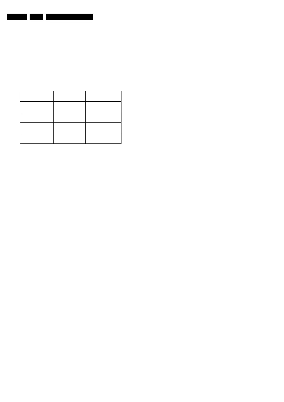
the CRTs screen. See table.
Table 9-1 Switching logic for Main and DW Picture
The source signals are fed directly to video processor IC7301.
The IC performs the source selection internally.
The video processor IC7301 decodes the CVBS at pin 24 or pin
29 into YC signals and further process it into YUV signal.
Output is at pins 40, 45, and 46.
The PIP-AUDIO signal is fed to pin 47 of the audio demodulator
MSP34xx on the SSB.
Note: When S-VHS is inserted from the rear, the AV2 source
will be disabled. Likewise, when S-VHS is inserted from the
side-AV.
9.3.4 DW/PIP processing
The SAB908x (IC7801) is a multi-standard PIP controller,
which can be used in double window or PIP applications. The
YUV signals from the video processor IC7301 are fed to pin 79,
81, and 83. The PIP controller will insert the YUV signals from
IC7301 with reduced size into the main picture. The main
picture YUV signals (50 Hz) are fed to pins 100, 2, and 98,
respectively. These signals are used during the DW mode.
Inside IC7801, the conversion to the digital environment is
done with ADCs. Processing and storage (1 MB DRAM) of the
video data is done entirely in the digital domain. The
conversion back to the analogue domain is done by DACs.
Internal clocks are generated by PLLs, which lock on to the
applied horizontal and vertical syncs from the main and sub
pictures. The main picture syncs are applied to pin 70 (V) and
pin 94 (H) and the sub picture syncs are applied to pin 72 (V)
and pin 87 (H).
For DW mode, the main picture is compressed horizontally by
a factor of two and fed directly to the output. After compression,
a horizontal expansion of two is possible for the main picture.
The sub picture is also compressed horizontally by a factor two,
but is stored in memory before it is fed to the outputs.
Post-processed YUV signals are fed to the "fast switching"
IC7803 (TDA8601 pins 6, 7, and 8). In normal operation
(without DW), the main picture YUV signals (at pins 2, 3 and 4)
are bypassed by IC7803, and returned back to the main video
processor. When DW mode is active, the compressed YUV
signals (main and sub pictures) are used and fed to the main
video processor. During the PIP mode, only sub-picture YUV
signals are used. The insertion control is made possible by a
fast blanking signal from pin 68 of IC7801.
9.3.5 Power supplies
The power supplies used by the DW panel are from the main
board 5 V, 8 V, and 33 V (for tuner only). IC7802 LM317T
regulates the 5V to +3.3V, +3V, and +3VD. These voltages are
mainly used by the DW processor circuitry. The 8V is mainly
supplied to the IF + video processing circuitry (IC7301
TDA888x), and to fast switching IC7803.
9.4 Abbreviation list
2DNR Spatial (2D) Noise Reduction
3DNR Temporal (3D) Noise Reduction
AARA Automatic Aspect Ratio Adaptation:
algorithm that adapts aspect ratio to
remove horizontal black bars; keeping
up the original aspect ratio
ACI Automatic Channel Installation:
algorithm that installs TV sets directly
from cable network by means of a
predefined TXT page
ADC Analogue to Digital Converter
AFC Automatic Frequency Control: control
signal used to tune to the correct
frequency
AGC Automatic Gain Control: algorithm that
controls the video input of the feature-
box
AM Amplitude Modulation
ANR Automatic Noise Reduction: one of the
algorithms of Auto TV
AR Aspect Ratio: 4 by 3 or 16 by 9
Artistic See OTC 2.5: main processor
ASF Auto Screen Fit: algorithm that adapts
aspect ratio to remove horizontal black
bars but without throwing away video
information
ATV See Auto TV
AUDIO_C Audio Centre
AUDIO_L Audio Left
AUDIO_R Audio Right
AUDIO_SL Audio Surround Left
AUDIO-SR Audio surround right
AUDIO_SW Audio Subwoofer
Auto TV A hardware and software control
system that measures picture content,
and adapts image parameters in a
dynamic way
BC-PROT Protection signal to the uP for a too
high Beam Current.
BG System B and G
BLC-INFO Black Current Info
B-SC1-IN Blue SCART1 in
B-SC2-IN Blue SCART2 in
B-TXT Blue teletext
BOCMA BiMOS One Chip Mid-end
Architecture: integrated video and
chroma decoder
CL Constant Level: audio output to
connect with an external amplifier
ComPair Computer aided rePair
CRT Cathode Ray Tube or picture tube
CSM Customer Service Mode
CTI Colour Transient Improvement:
manipulates steepness of chroma
transients
CVBS Composite Video Blanking and
Synchronisation
CVBS-TER CVBS terrestrial
DAC Digital to Analogue Converter
DBE Dynamic Bass Enhancement: extra
low frequency amplification
DC-filament Filament supply voltage
SEL-TUNER1(Pin
6 IC7403)
SEL TUNER2
(Pin 7 IC7403)
Selected CVBS
signals
0 0 Main = Tuner 1
DW/PIP = Tuner 2
0 1 Main = Tuner 1
DW/PIP = Tuner 1
1 0 Main = Tuner 2
DW/PIP = Tuner 2
1 1 Main = Tuner 2
DW/PIP = Tuner 1