Service Modes, Error Codes, and Fault Finding
EN 28 EM5.1E5.
contents of the error buffer (this works in "normal
operation" mode and in "protection" mode).
• Transmit the commands "MUTE" - "062500" - "OK" with a
normal RC. The complete error buffer is shown. Take
notice that it takes some seconds before the blinking led
LED starts.
• Transmit the commands "MUTE" - "06250x" - "OK" with a
normal RC (where "x" is a number between 1 and 5). When
x= 1 the last detected error is shown, x= 2 the second last
error, etc.... Take notice that it takes some seconds before
the blinking led LED starts.
• "DIAGNOSE X" with the DST (where "x" is a number
between 1 and 5). When x= 1 the last detected error is
shown, x= 2 the second last error, etc.... When x = 0 all
errors are shown.
5.7 Protections
5.7.1 Introduction
This chassis has only one microprocessor (OTC), which
remains active during Standby. This because power of the
microprocessor and the attached memory chip set is coming
from the 3V3 supply, which is derived from the 5V Standby-
circuitry. Therefore, in both Power-on as in Standby mode, the
microprocessor is connected to this power supply.
If a fault situation is detected, an error code will be generated
and if necessary, the set is put in protection mode. The
protection mode is indicated by the blinking of the front LED at
a frequency of 3 Hz (or by a coded blinking in special cases).
In some error cases however, the microprocessor does not put
the set in the protection mode (this is the case with the -
hardware - loudspeaker protection of the audio amplifier).
The content of the error buffer can be read via the service menu
(SAM), the blinking LED procedure or via DST/ComPair.
To get a quick diagnosis, this chassis has three service-modes
implemented:
• The Customer Service Mode (CSM).
• The Service Default Mode (SDM). Start-up of the set in a
predefined way.
• The Service Alignment Mode (SAM). In this mode, items
of the set can be adjusted via a menu.
You can enter both SDM and SAM modes via the 'service pads'
on the SSB, via an RC-transmitter (DST or standard RC), or via
ComPair. It is not possible to enter the SAM in "standby"; the
TV has to be in "normal operation" mode.
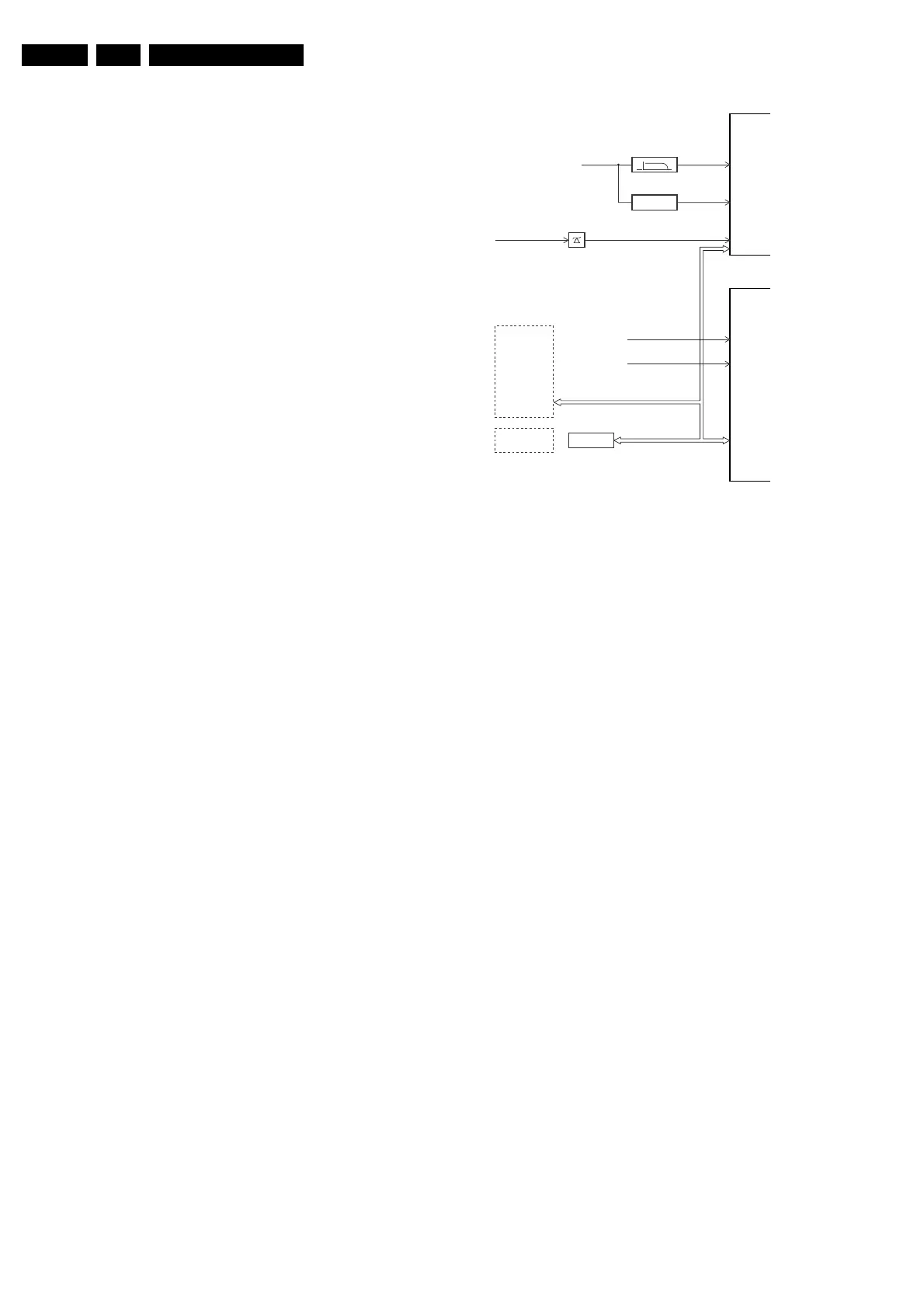
The "Protection Diagram" shows the structure of the protection
system. See diagram below.
Figure 5-3 Protection diagram
There are several types of protections:
• I2C related protections.
• OTC related protections (via polling on I/O pins or via
algorithms).
• HOP related protections (mainly for deflection items).
• Hardware errors that are not sensed by the OTC (e.g.
vertical flyback protection, bridge coil protection, E/W
protection, arcing protection).
All protections are explained below.
5.7.2 I2C Related Protections
In normal operation, some registers of the I2C controlled ICs
are refreshed every 200 ms. During this sequence, the I2C
busses and the I2C ICs are checked.
An I2C protection will take place if the SDA and SCL lines are
short-circuited to ground, or to each other. An I2C error will also
occur, if the power supply of the IC is missing (e.g. FBX_PROT
(error 16)).
5.7.3 OTC Related Protections
If a protection is detected at an OTC input, the OTC will start to
scan all protection inputs every 200 ms for 5 times. If the
protection on one of the inputs is still active after 1 s, the
microprocessor will put the set in the protection mode.
Before the scanning is started, a so-called "ESD refresh" is
carried out. This is done, because the interrupt on one of the
inputs is possibly caused either by a flash or by ESD. As a flash
or ESD can influence IC settings, the HIP, MSP, 3D Comb (US
only) and wireless module are initialised again, to ensure the
normal picture and sound conditions of the set.
8 V and 5 V protection: The microprocessor senses the
presence of the 8 V and 5 V (via the "+5V_CON" and
"+8V_CON" lines). If one (or both) of these voltages is (are) not
present, an error code is stored in the error buffer of the NVM,
and the set is put in the protection mode.
5.7.4 HOP Related Protections
Every 200 ms, the status register of the HOP is read by the
OTC (via the I2C bus). If a protection signal is detected on one
XPR (43)
7301
7001
FLS (5)
HFB-XRAY-PROT
HOP
+8V SENSE (105)
+5V SENSE (106)
OTC
EHT-info
HFB
+5V_CON
+8V_CON
Flash detect
I
2
C
I
2
C PROTECTIONS
HIP
HOP
PICNIC
TUNER
NVM
DNR
MSP
TOPIC
I
2
C
I
2
C
PICNIC 3V3
FBX
PROTECTION
CL 16532044_024.eps
090501