Do you have a question about the Philips FWM390 and is the answer not in the manual?
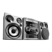
| woofer size | 5.25 inches |
|---|---|
| tweeter size | 2 inches |
| polydome piezo size | 1 inch |
| RMS power | 2x60 W |
|---|---|
| music power | 2x120 W |
| eco power standby | 1 watt |
| headphone jack size | 3.5 mm |
|---|---|
| other connections | FM Antenna, MW Antenna |
Warnings in multiple languages regarding sensitivity of components to ESD and necessary precautions.
Information on laser product safety and general regulations for repair and part replacement.
Overview of main buttons for power, source selection, playback, and sound settings.
Solutions for problems like no disc display, poor radio reception, tape issues, and remote control malfunction.
Instructions for removing the CD changer module and the front panel assembly.
Procedures for removing the front board and rear panel components, including specific screw references.
Steps for loosening and removing the ETF tape module using screws.
Steps for initiating the service test program and specific frequencies for tuner alignment.
Instructions for activating DEMO mode and interpreting error codes displayed during service tests.
A schematic showing the signal flow and interconnections of the AF9 board.
Detailed wiring diagram illustrating connections between various modules and boards.
Schematic and component/chip layout for the headphone amplifier section.
Schematic diagram, component views, and legend for the ECO6 Cenelec tuner board.
Adjustment procedures and voltage measurements for tuning various bands on the Cenelec tuner.
Layout diagrams showing component placement and copper traces for the ECO6 Cenelec tuner board.
Describes the function of major ICs, bias level adjustment, motor speed control, and Dolby circuit.
Exploded view of the tape mechanism and a table for motor speed, wow/flutter, azimuth, frequency response, and bias adjustments.
Diagram showing the placement of components on the tape module's PCB.
Sections covering CD and MP3 part component layouts and circuit diagrams.
Critical warnings and steps for replacing the CD mechanism, emphasizing ESD protection and capacitor discharge.
Provides a brief description of the power amplifier module's circuitry and operation.
Details on how the different DC supply voltages for the Super Class G amplifier are generated.
Block diagram showing the mains input, standby circuit, and power distribution.
Block diagram illustrating the power amplifier stages, regulators, and control lines.
Details the functions of TDA7468D, MIC MIXING, DPL Interface, Line Out, Sub-woofer Out, IS, Headphone Amp, M62320FP, CD Standby, and CD Digital Out.