the MAIN-CVBS-EXT-IN. The MAIN-CVBS-
EXT-IN is selected composite Video or
Luminance from either AV1, AV2, or AV3.
These signals are selected by the Switch IC
7401 which is controlled by two lines from the
Microprocessor, which are SEL-MAIN-R1R2
and SEL-MAIN-FRNT-RR. If SVHS is the
selected input, the Y (Luminance signal) is fed
to Pin 29 by 7401. Selected Video or Y from
7301 is output on Pin 54 and is buffered by
7421. If the output of 7301 is Composite
Video, the Comb Filter IC 7405 will output Y
and C on Pins 15 and 13. Switching IC 7407
selects YC from either the Comb Filter or Y
from 7421. If one of the SVHS inputs is
selected, 7401 outputs C (Chrominance) on
Pin 14 and is buffered by 7412-B before being
fed to 7407. IC 7407 is switched by Pin 22 of
7301. A High on Pin 22 causes Pins 12 and
13 to switch the inputs on Pins 1 and 11.
When Pin 22 is Low, 7425 is turned Off
switching Pins 5 and 6 High, selecting the
inputs on Pins 4 and 8. Selected YC is then
fed to Pins 21 and 20 of 7301 where they are
fed to a Delay Line and Demodulator. The
output of the Demodulator and Delay Line is
fed to a YUV switch, which selects between
this signal and external YUV (Component
Input) from the Jacks on the Large Signal
panel. The selected YUV signal is then fed
back into 7301 on Pins 39, 47, and 48. The
signal is then fed to a YUV processing circuit
and to an RGB Matrix where OSD (On Screen
Display) is added. The signal is then fed
to the RGB output circuit and to the CRT.
A Test Waveform is first sent to the CRT
on the RGB lines. When this Test Signal is
detected by the CRT drive circuits, the
signal is fed back to 7301 on Pin 3 on the
CUTOFF LINE. When these are detected,
the Video signal is then output on the
RGB lines.
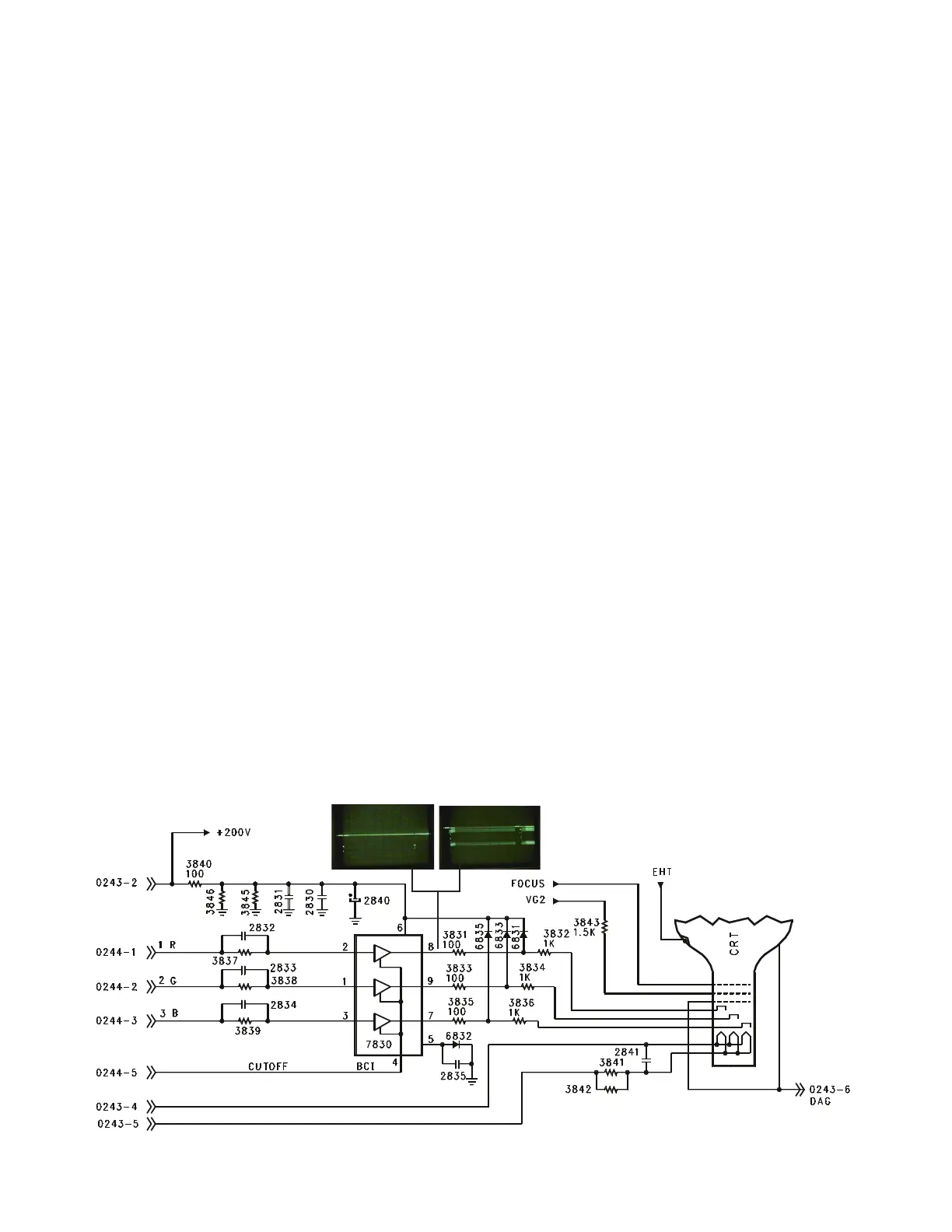
Standard CRT Drive (Figure 9)
The CRT drive signal is fed to 7830 which
drives the CRT. As mentioned previously,
a Test Signal is sent to 7830 and to the
CRT. The Waveform on the left shows this
Test Signal. When 7830 senses the
correct current flow in the CRT, the Test
Signal is sent to the SSB via the CUTOFF
line. The Picture RGB signal is then fed to
the CRT Board. This waveform is shown
on the right. If the CRT is defective or
unplugged, no pulse will be ouput on Pin 4.
Therefore, the Signal Processor IC on the
SSB will not output the Video Signal on the
RGB lines.
Figure 9 - Standard CRT Drive Circuit
Page 12