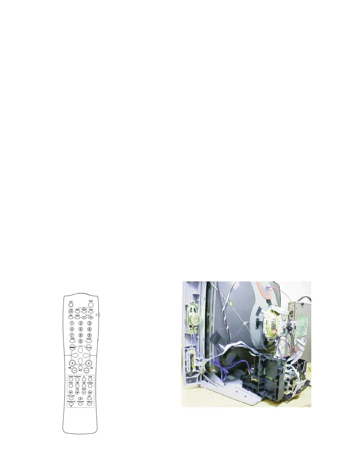
PIP (Picture in Picture) Video Flow (Figure
10)
There are two PIP chassis versions which are
the Single Tuner and Two Tuner sets. Video
Signal flow for the Single Tuner PIP version is
the same as the Two Tuner version, except
the Composite Video from Pin 16 of 7301 is
routed through the Large Signal Board (LSB)
to the PIP module and back to the 1333
Sound Trap in the Two Tuner version. In the
Single Tuner version, Video from Pin 16 is
routed through jumper 4308. The second
Tuner is located on the PIP panel. Baseband
audio is output on Pin 27 and is buffered by
7331. In the Two Tuner version, the Audio is
combined with the composite video before
being fed to the PIP panel. Selected Video
with the Baseband Audio from the PIP panel
is fed through jumper 4307 to the Audio
Processor. In the Single Tuner version,
Baseband Audio from 7331 is fed through
jumper 4304 to the Audio Processor. YUV
signal from Pins 40, 45, and 46 are routed
through the PIP module where the PIP
window Video is inserted. Other Video signal
flows are the same as for the Non-PIP
version. The Single and Two Tuner PIP
circuits are the same except for the addition of
the second Tuner and Signal processing
circuits on the PIP panel.
PIP Circuit (Figure 11)
The PIP comes in two versions, Single
Tuner with no tuner on the PIP panel and
two tuner versions with the second tuner
located on the PIP module. Output of the
second tuner is fed to the SAW FILTER
1901, and to the Signal Processor 7914.
Composite Video is fed to the Switch 7916
which selects between the PIP tuner or
selected Composite Video from the SSB.
There are two sets of switches: one to
select Video for the main picture, CVBS-
PIP_TUN1-2-CVBS-IN, and one to select
Video for the PIP window. Selected Video
for the PIP window is fed to 7801, which
selects between the output of 7916 or from
AV1, AV2, or the Side Jack panel (labeled
Front In). The output of 7801 is buffered
by a four transistor amplifier and then fed
to Pin 22 of 7803, PIP processor. The PIP
processor is controlled by the I2C buss
(SDA and SCL). It is kept in sync by the
Vertical sync pulse (VFB) and the
Horizontal sync pulse (SANDCASTLE).
The PIP window video is output as YUV to
the YUV switch, 7919. The signal is
combined with the main picture YUV from
Page 15
Model 27PT81 - Very Flat CRT - Two
Tuner PIP