SWEEP AND SHUTDOWN CIRCUITS
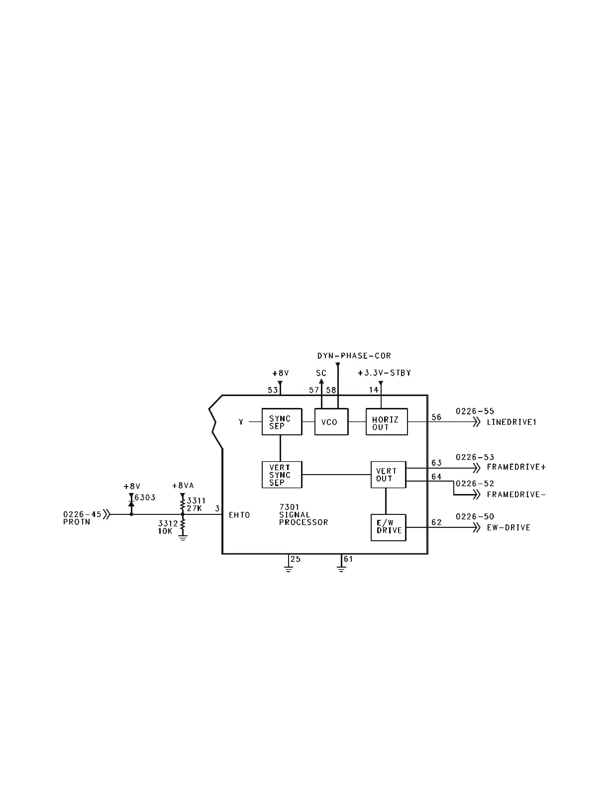
Horizontal and Vertical Drive (Figure 5)
The 3.3 volts Standby supply provides power
to 7301 on Pin 14 for a Horizontal Soft Start.
The Standby line from the Microprocessor
turns the +8 volt supply On to provide power
for the Sync circuits when the set is turned
On. The Horizontal Output on Pin 56 is
switched On by the Microprocessor via the
I2C buss, after the Soft Start is complete.
Vertical Drive, labeled Frame-Drive, is output
on Pins 63 and 64. In the event the Vertical
Output should fail, the Signal Processor 7301
will blank the RGB output. East-West Drive
on Pin 62 provides linearity correction for the
Very Flat and Larger CRTs. Sandcastle is
output on Pin 57. The Dynamic Phase
Correction input on Pin 58 has two functions.
One function is to provide Horizontal
Phase correction for the Horizontal Drive.
The other is to provide Flash protection in
case of an overvoltage on the I-Beam line.
If the pulse on Pin 58 exceeds 6 volts,
Horizontal Drive will be shut Off. It will be
necessary to recycle power to the set to
restore operation. This failure will
generate an error code 1 indicating a
problem with the Horizontal Output
Transformer or with the CRT drive circuit.
The PROTN line is connected to the
IBEAM (Dag) line. This voltage is used to
make minor adjustments in the Vertical
Drive to compensate for minor changes in
Beam Current. This line is also connected
to the Overvoltage Detection circuit. If this
voltage exceeds 3.9 volts, the Horizontal
Drive will be shut Off. The Microprocessor
will show an error code 3.
Horizontal Output and Shutdown (Figure 6)
Horizontal Drive (LINEDRIVE1) is fed to
transistor 7481 and coupled through
transformer 5406 to the Horizontal Output
transistor 7410. In sets with the Very Flat
CRT and larger screen sizes, an East West
Drive circuit is present. The East West
Drive circuit also has a protection circuit to
detect the loss of Horizontal drive. In nor-
mal operation, 7470 is switched by the
EW-Drive. The pulse width is too narrow
to develop the necessary voltage to turn
7478 On. Current flow through 3479
keeps transistor 7480 turned On, keeping
Figure 5 - Horizontal and Vertical Drive
Page 7