Mechanical Instructions
EN 41L01.1U AC 4.
4.3 Assembly/Board Removal
4.3.1 Comb Filter Assembly/Board (if present)
You can remove the Comb Filter panel from the family board by
disconnecting it from connector 1810 (located at the top of the
AC power transformer 5520).
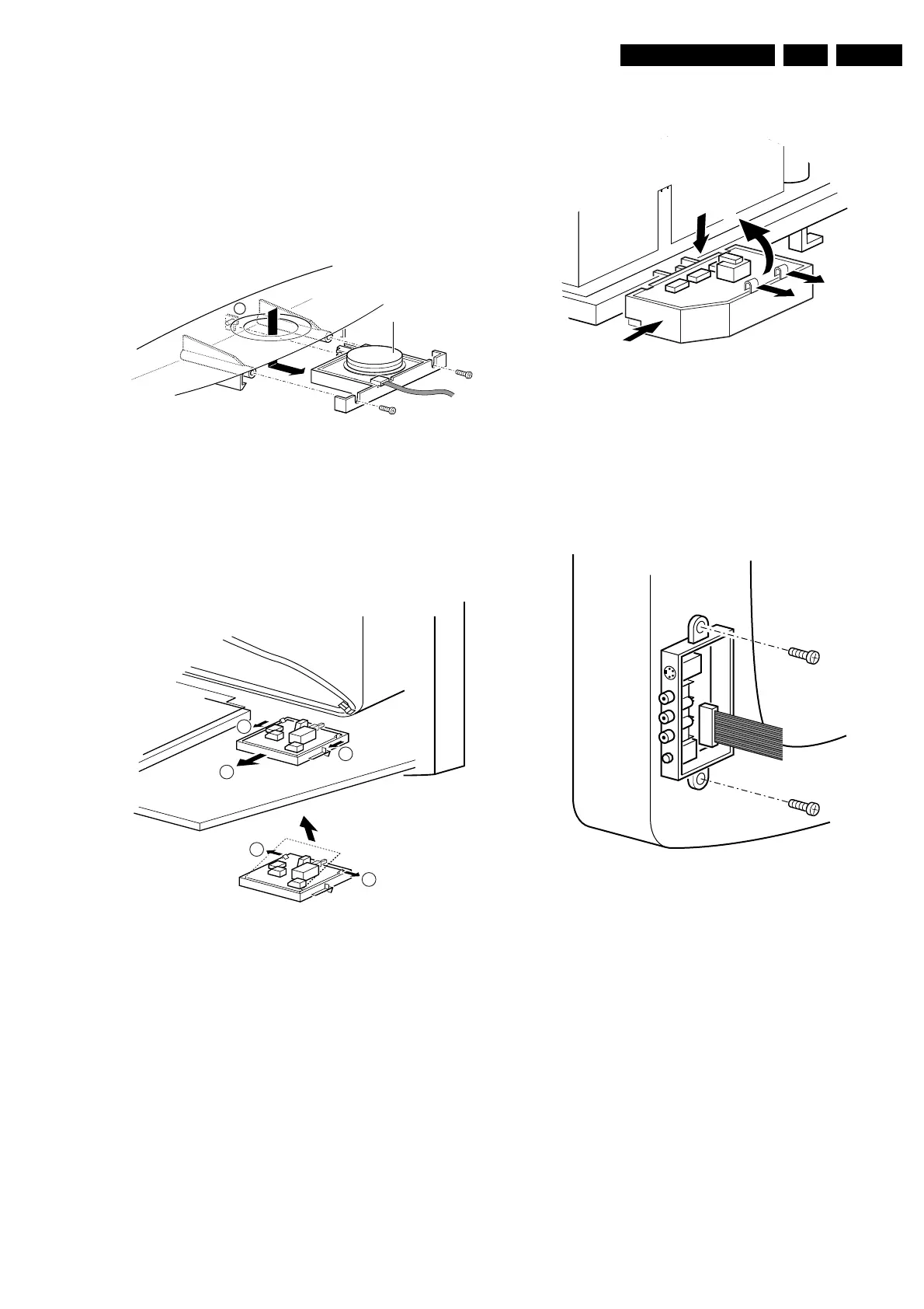
4.3.2 Top Control Assembly/Board (if present)
Figure 4-3 Top control removal
1. Remove the two screws (if present).
2. Pull the module down and backward (release it from the
front hinge [M]).
3. Lift the board from its bracket while releasing the two
fixation clamps. The board hinges on the other side.
4.3.3 Front Interface Assembly/Board (if present)
Figure 4-4 Front interface removal
1. You can remove the complete module from the bottom
plate, by pulling the two clamps upward [1[ while sliding the
module away from the CRT [2].
2. Release the 2 clamps [3] at the side of the bracket, and lift
the board out of the bracket (it hinges at one side).
4.3.4 DAF Assembly/Board (if present)
Figure 4-5 DAF panel removal
1. You can remove the complete module from the family
board bracket, by pressing the clamp downward [1] while
sliding the module toward the CRT [2].
2. Release the 2 clamps [3] to lift the board out of the bracket
[4].
4.3.5 Side Jack Panel Assembly/Board (if present)
Figure 4-6 Side jack panel removal
1. You can remove the complete side jack panel assembly by
removing the 2 screws.
2. Release the 2 clamps to lift the board out of the bracket.
4.4 Set Re-assembly
Before replacing the back cover, check the following:
1. Be sure the AC power cord is mounted correctly in its
guiding brackets.
2. Re-place the strain relief for the AC power cord into the
cabinet.
3. Be sure all cables are returned to their original positions.
CL 06532012_003.eps
030200
M
Top control board
2
3
1
1
3
CL 06532130_018.eps
021000
CL 26532119_060.eps
181202
3
2
3
4
1
CL 06532012_004.eps
030200
www.freeservicemanuals.info
Published in Heiloo Holland
 Loading...


