Circuit Description
EN 93L01.1U AC 9.
9. Circuit Description
Index of this chapter:
1. Introduction
2. Audio Signal Processing
3. Video Signal Processing
4. Synchronization
5. Deflection
6. Power Supply
7. Control
8. Abbreviations
9. IC Data Sheets
Notes:
• For a good understanding of the following circuit
descriptions, please use the block diagram in chapter 6,
and/or the electrical diagrams in chapter 7. Where
necessary, you will find a separate drawing for clarification.
• Figures below can deviate slightly from the actual situation,
due to different set executions.
9.1 Introduction
The 'L01.1U AC' chassis is a global TV chassis for the model
year 2003 and is used for TV sets with screen sizes from 20" -
32" (large screen), in Super Flat, Real Flat, and Wide Screen
executions. In comparison to its predecessor (the 'L01.1U AB'),
the chassis has enhanced features like a 2D 3-line Comb-filter
and 'Active Control'.
The standard architecture consists of a Mono Carrier, a Picture
Tube panel, a Side I/O panel, and a Top Control panel.
The Mono Carrier consists primarily of conventional
components with hardly any surface mounted devices.
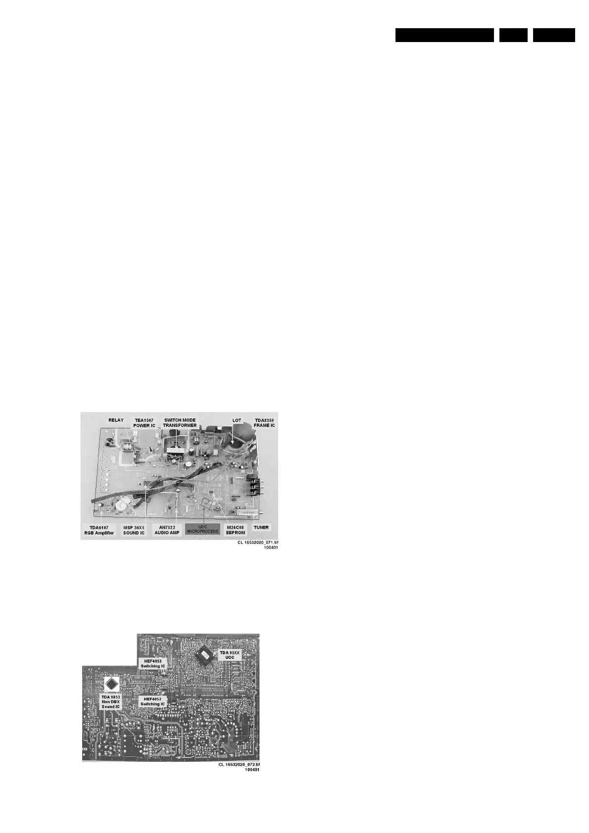
Figure 9-1 Mono Carrier component side
The functions for video processing, microprocessor (P), and
teletext (TXT) decoder are combined in one IC (TDA958xH),
the so-called Ultimate One Chip (UOC). This chip is (surface)
mounted on the copper side of the LSP.
Figure 9-2 Mono Carrier solder side
The 'L01.1U AC' is divided into 2 basic systems, i.e. mono and
stereo sound. While the audio processing for the mono sound
is done in the audio block of the UOC, an external audio
processing IC is used for stereo sets.
The tuning system features 181 channels with on-screen
display. The main tuning system uses a tuner, a
microcomputer, and a memory IC mounted on the Mono
Carrier.
The microcomputer communicates with the memory IC, the
customer keyboard, remote receiver, tuner, signal processor IC
and the audio output IC via the I
2
C bus. The memory IC retains
the settings for favorite stations, customer-preferred settings,
and service / factory data.
The on-screen graphics and closed caption decoding are done
within the microprocessor, and then sent to the signal
processor IC to be added to the main signal.
The chassis utilizes a Switching Mode Power Supply (SMPS)
for the main voltage source. The chassis has a 'hot' ground
reference on the primary side and a cold ground reference on
the secondary side of the power supply and the rest of the
chassis.
9.2 Audio Signal Processing
9.2.1 Stereo
In stereo sets, the signal goes via the SAW filter (position 1002/
1003), to the audio demodulator part of the UOC IC 7200. The
audio output on pin 33 goes to the stereo decoder 7831/ 7861.
The switch inside this IC selects either the internal decoder or
an external source.
There are two stereo decoders versions used:
1. A BTSC DBX stereo/SAP decoder (MSP34X5 at position
7831) for the highest specified sets, and
2. A BTSC non-DBX stereo decoder (TDA9853 at position
7861) for BTSC Economic.
The output is fed to the to the audio amplifier (AN7522 at
position 7901). The volume level is controlled at this IC (pin 9)
by a control line (Volume|Mute) from the microprocessor. The
audio signal from 7901 is then send to the speaker and
headphone output panel.
www.freeservicemanuals.info
Published in Heiloo Holland



 To Next Page