Service Modes, Error Codes and Fault Finding
EN 46 L01.1U AC5.
the repair. This ensures that old error codes are no longer
present.
If possible, check the entire contents of the error buffer. In
some situations, an error code is only the result of another error
and not the actual cause of the problem (for example, a fault in
the protection detection circuitry can also lead to a protection).
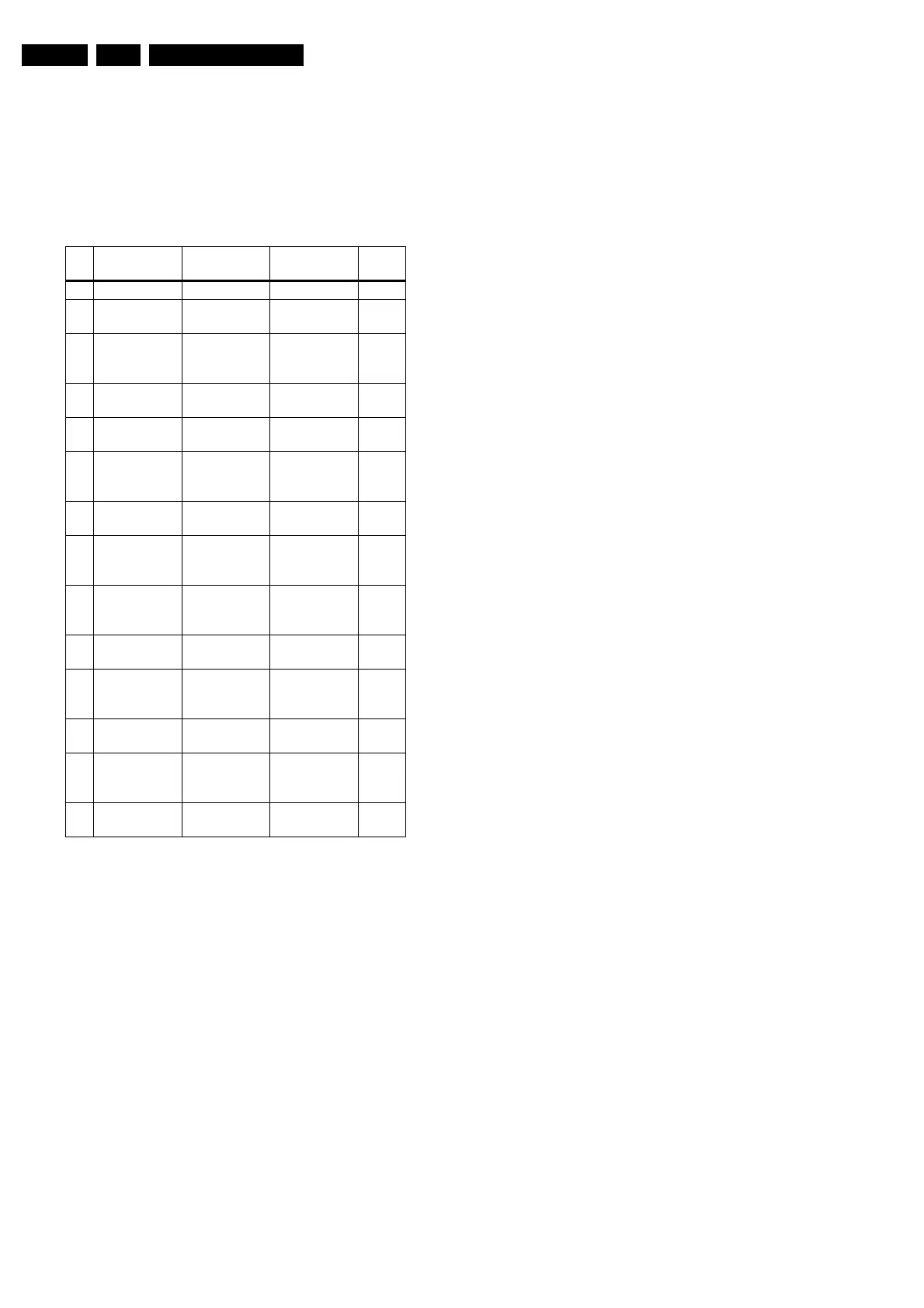
Table 5-3 Error code overview
Note: Error 7 is not applicable.
5.6 The Blinking LED Procedure
Using this procedure, you can make the contents of the error
buffer visible via the front LED. This is especially useful when
there is no picture.
When the SDAM is entered, the LED will blink the contents of
the error-buffer:
• 1-14 short blinks (indicates error number 1-14),
• When all the error-codes are displayed, the sequence
finishes with an 'on' LED blink of 1.5 seconds,
• The sequence starts again.
Example of error buffer: 12 9 6 0 0
After entering SDAM, the following occurs:
• 1 long 'on' blink of 5 seconds to start the sequence,
• 12 short blinks followed by a pause of 1.5 seconds,
• 9 short blinks followed by a pause of 1.5 seconds,
• 6 short blinks followed by a pause of 1.5 seconds,
• 1 long 'on' blink of 1.5 seconds to finish the sequence,
• The sequence starts again at 12 short blinks.
5.7 Protections
If a fault situation is detected, an error code will be generated;
and, if necessary, the television set will go into protection
mode. Blinking of the red LED at a frequency of 3 Hz indicates
the protection mode. In some error cases, the microprocessor
does not put the set in protection mode. The error codes of the
error buffer and the blinking LED procedure can be read via the
Service Default Alignment Menu (SDAM), or via ComPair.
To get a quick diagnosis the chassis has two service modes
implemented:
• The Customer Service Mode (CSM).
• The Service Default Alignment Mode (SDAM).
For a detailed description, see the “Customer Service Mode”
and “Service Default Alignment Mode” sections.
5.8 Repair Tips
Below some failure symptoms are given, followed by a repair
tip.
• Set is dead and makes hiccupping sound. 'Main Power
Supply' is available. Hiccupping stops when L5561 is de-
soldered, meaning that problem is in the 'Main Power
Supply' line. No output voltages at LOT, no horizontal
deflection. Reason: line transistor 7460 is defective.
• Set is dead, and makes no sound. Check power supply
IC 7520. Result: voltage at pins 1, 3, 4, 5 and 6 are about
180 V and pin 8 is 0 V. The reason why the voltage on
these pins is so high is that the output driver (pin 6) has an
open load. That is why MOSFET 7521 is not able to switch.
Reason: feedback resistor 3523 is defective. Caution: Be
careful measuring the gate of 7521: circuitry is very high
ohmic and can easily be damaged!
• Set is in hiccup mode and shuts down after 8 seconds.
The blinking LED (set is in SDAM mode) indicates error 5.
As it is unlikely that the microprocessor 'POR' and '+8V
protection' happen at the same time, measure the '+8V'
supply. If this voltage is missing, check transistor 7480.
• Set is in non-stop hiccup mode. Set is in over-current
mode; check the secondary sensing (opto coupler 7515)
and the 'Main Power Supply' voltage. Signal 'Stdby_con'
must be logic low under normal operation conditions and
goes to high (3.3 V) under standby and fault conditions.
• Set turns on, but without picture and sound. The screen
shows snow, but OSD and other menus are okay. Blinking
LED procedure indicates error 11, so problem is expected
in the tuner (part reference number 1000). Check presence
of supply voltages. 'Vlotaux+5V' voltages at pin 5 and 7 are
okay; 'VT_supply' at pin 9 is missing. Conclusion: resistor
3460 is defective.
• Set turns on, but with a half screen at the bottom.
Sound is okay. Blinking LED (set is in SDAM mode)
indicates error 3. Check 'Vlotaux+11V' and '+50V'. If they
are okay, problem is expected in the vertical amplifier IC
7471. Use an oscilloscope to measure the waveform on pin
17 of the UOC. Also, measure the waveform at pin 1 of IC
7471. If the signal there is missing, a defective resistor
R3244 caused the problem.
Er-
ror
Device Error descrip-
tion
Check item Dia-
gram
0- No Error
1 - X-Ray Protec-
tion (USA)
2465, 7460 A2
2 - Horizontal
Protection
7460, 7461,
7462, 7463,
6467
A2
3 TDA8359TDA
9302
Vertical Pro-
tection
7861, VlotAux
+13v
A2, A3
4 MSP34X5TDA
9853
MAP I
2
C iden-
tification error
7831, 7861 A9 or
A11
5 TDA95XX POR 3.3V / 8V
Protection
7200, 7560,
7480
A1, A2.
A5, A6,
A7
6I
2
C bus General I
2
C
bus error
7200, 3624,
3625
A7
7 - Power Down
(over current)
prot.
--
8 - E/W Protec-
tion (Large
Screen)
7400, 3405,
3406, 3400
A2
9 M24C08 NVM I
2
C iden-
tification error
7602, 3611,
3603, 3604
A7
10 Tuner Tuner I
2
C
identification
error
1000, 7482 A2, A4
11 TDA6107/8 Black current
loop protection
7330, RGB
amps, CRT
B1, B2
12 M65669 MAP I
2
C iden-
tification error
(USA)
7803 P
14 DVD Loader DVD I
2
C iden-
tification error
DVD Interface
module
DVD
Loader
www.freeservicemanuals.info
Published in Heiloo Holland
 Loading...


