Circuit Description
EN 95L01.1U AC 9.
9.3 Video Signal Processing
9.3.1 Introduction
The video signal-processing path consists of the following
parts:
• RF signal processing.
• Video source selection.
• Video demodulation.
• Luminance / Chrominance signal processing.
• RGB control.
• RGB amplifier
The processing circuits listed above are all integrated in the
UOC TV processor. The surrounding components are for the
adaptation of the selected application. The I
2
C bus is for
defining and controlling the signals.
9.3.2 RF Signal Processing
The incoming RF signal goes to the tuner (pos. 1000), where
the 45.75 MHz IF signal is developed and amplified. The IF
signals then exits the tuner from pin 11 to pass through the
SAW filter (pos. 1002/1003). The shaped signal is then applied
to the IF processor part of the UOC (pos. 7200).
Tuner AGC (Automatic Gain Control) will reduce the tuner gain
and thus the tuner output voltage when receiving strong RF
signals. Adjust the AGC takeover point via the Service
Alignment Mode (SAM). The tuner AGC starts working when
the video-IF input reaches a certain input level and will adjust
this level via the I
2
C bus. The tuner AGC signal goes to the
tuner (pin 1) via the open collector output (pin 22) of the UOC.
The IC also generates an Automatic Frequency Control (AFC)
signal that goes to the tuning system via the I
2
C bus, to provide
frequency correction when needed.
The demodulated composite video signal is available at pin 38
and then buffered by transistor 7201.
9.3.3 Video Source Selection
The Composite Video Blanking Signal (CVBS) from buffer
7201 goes to the audio carrier trap filters 1200, 1201, or 1202
(depending on the system used), to remove the audio signal.
The signal then goes to pin 40 of IC 7200. The internal input
switch selects the following input signals:
• Pin 40: terrestrial CVBS input
• Pin 42: external AV1 CVBS input
• Pin 44: external Side I/O CVBS or AV2 (or comb filter)
luminance (Y) input
• Pin 45: external AV2 (or comb filter) chrominance (C) input
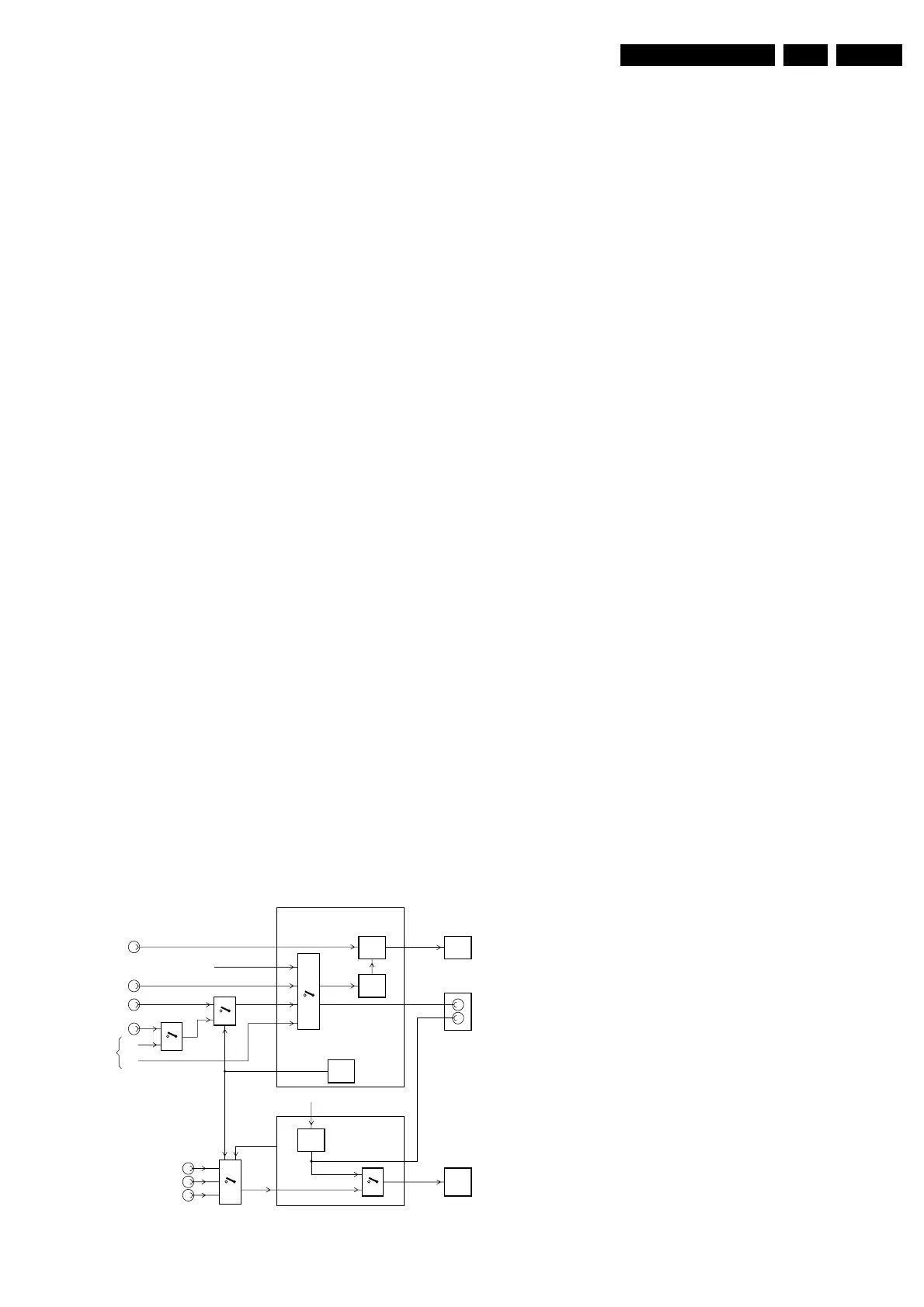
Figure 9-5 Video source selection
Once the signal source is selected, a chroma filter calibration is
performed. The received color burst sub-carrier frequency is
used for this. Correspondingly, the chroma band pass filter for
PAL/NTSC processing or the cloche filter for SECAM
processing is switched on. The selected luminance (Y) signal
is supplied to the horizontal and vertical synchronization circuit
and to the luminance processing circuit. In the luminance-
processing block, the luminance signal goes to the chroma trap
filter. This trap is switched 'on' or 'off' depending on the color
burst detection of the chroma calibration circuit.
The group delay correction part can be switched between the
BG and a flat group delay characteristic. This has the
advantage that in multi-standard receivers no compromise has
to be made for the choice of the SAW filter.
9.3.4 Comb Filter
Introduction
The video signal prepared for broadcast contains two major
parts commingled, the luminance (makes a black and white
picture in full detail) and chrominance (coloration with not quite
all the detail). This method is used instead of red, green, and
blue sub-signals in order to get the best looking picture that can
be transmitted in the limited bandwidth of the broadcast
channel.
Every TV receiver and VCR must contain a filter to separate the
luminance and color (Y and C) again. Less than perfect Y/C
separators lose resolution -- horizontal, vertical, or both. Also
there are artifacts such as rainbow swirls where thin stripes
should be, and crawling dots where patches of different colors
meet. The perfect Y/C separator does not exist yet, although
some 3D comb filters come close.
There are several methods for filtering:
• No comb filter. The cheapest solution is to use simple
filters (notch, low pass, bandpass filters) that pass only the
coarse and medium horizontal detail (lower 3 MHz or so) to
the luminance circuits and pass the bulk of the color
information still commingled with the fine luminance detail
(3 to 4.2 MHz) to the color circuits.
• Two line ordinary filter. The improvements over 'no'
comb filter are: revealing of finer horizontal detail overall,
and some reduction of rainbow swirls. Improvement of fine
detail is most prominent where details consist of upright
dark and light lines.
• Three line ordinary filter. Improvement over the two line
filter consists of sharper transition from one color to
another at sharp horizontal color boundaries, and less dot
crawl.
• Three line adaptive (a.k.a. 2D; dynamic) filter. This
method adapts the mixing according the line content of two
fields. The big improvement that the 2D comb filter brings,
is the elimination (or near elimination) of dot crawl. This
type of filter is used in the 'L01.1U AC' chassis. When
present, the filter CBA is plugged-in on connector 1810B of
the Mono Carrier.
• Motion adaptive (3D) filter. The difference with the 2D
method is that this method uses three fields, so it also uses
'time' dimension. The 3D comb filter can achieve
essentially perfect Y/C separation, eliminating all dot crawl
and rainbow swirls for 'stationary' subject material, and
perform at least as well as the 2D filter for the rest of the
picture.
Implementation
The input (CVBS) signal comes from pin 47 of the the UOC. On
the comb filter panel, it first enters a low-pass filter (items 2409,
5408, 2408, 5407, and 2407) and an amplifier circuit (items
7401 and 7402). The LPF is used to eliminate the noise and the
amplifier circuit to get a video input of 1 V
PP
.
The 'REF0' subcarrier reference (f
SC
) is fed to pin 11 and
internally multiplied by four (4 x 3.58 MHz = 14.32 MHz) for the
system clock.
1,12
2,15
5,14
FRONTAUDIOIN
AV1AUDIOIN
AV1AUDIOIN
7801
3,13
7802
7901
47
30,31
7831
CL16532016_011.eps
120401
RGB/YUV
INSERT
RGB
56˜58
VIDEO
PROC.
AUDIO
AMPL.
42
7200
V-OUT
L/ROUT
UOC
µP
CRT
PANEL
MON.OUT
MAIN_OUT
24,25
SOUND
DEC
44
C-IN45
SY_CVBS_IN
9
70
SEL-MAIN-FRNT-RR
QSS_AM_DEM_OUT
4
910
SC2-CTRL
40
AV1_CVBS1_1
51˜53
RGB/YUV_IN
CVBS_FRONT_IN
0225-B
AV2CVBS_IN
SVHS
Y_IN
C_IN
INTERNAL_CVBS_IN
41,42
SC1-IN
47
www.freeservicemanuals.info
Published in Heiloo Holland
 Loading...


