Circuit Description
EN 98 L01.1U AC9.
voltage capacitors are considerable charged. At that point in
time, the deflection coil excites through C2465. This current
peak, through the high-voltage capacitor, distorts the flyback
pulse. This causes synchronization errors, causing an
oscillation under the white line.
During t3 - t5, C2490//2458 is charged via R3459. At the
moment of the flyback, C2490//2458 is subjected to the
negative voltage pulses of the parabola as a result of which
D6465 and D6466 are conducting and C2490//2458 is
switched in parallel with C2456//2457. The high-voltage diodes
are conducting this moment. Now extra energy is available for
excitation through C2465 and the line deflection.
Consequently, the flyback pulse is less distorted.
The S-Correction
Since the sides of the picture are further away from the point of
deflection than from the center, a linear sawtooth current would
result in a non-linear image being scanned (the center would
be scanned slower than the sides). For the center-horizontal
line, the difference in relation of the distances is larger then
those for the top and bottom lines. An S-shaped current will
have to be superimposed onto the sawtooth current. This
correction is called finger-length correction or S-correction.
C2456//2457 is relatively small, as a result of which the
sawtooth current will generate a parabolic voltage with
negative voltage peaks. Left and right, the voltage across the
deflection coil decreases, and the deflection will slow down; in
the center, the voltage increases and deflection is faster. The
larger the picture width, the higher the deflection current
through C2456//2457. The current also results in a parabolic
voltage across C2484//2469, resulting in the finger length
correction proportionally increasing with the picture width. The
east/west drive signal will ensure the largest picture width in the
center of the frame. Here the largest correction is applied.
East/West Correction
In this chassis, there are three types of CRTs, namely the 100º,
110º and wide screen CRTs. The 100º CRT is raster-
correction-free and does not need East/West correction.
The 110º 4:3 CRT comes with East/West correction and East/
West protection.
The wide screen TV sets have all the correction of the 110 4:3
CRT and also have additional picture format like the 4:3 format,
16:9, 14:9, 16:9 zoom, subtitle zoom and the Super-Wide
picture format
A line, written at the upper- or lower side of the screen, will be
larger at the screen center when a fixed deflection current is
used. Therefore, the amplitude of the deflection current must
be increased when the spot approaches the center of the
screen. This is called the East/West or pincushion correction.
The 'Ewdrive' signal from pin 15 of IC 7200 takes care for the
correct correction. It drives FET 7400. It also corrects breathing
of the picture, due to beam current variations (the EHT varies
dependent of the beam current). This correction is derived from
the 'EHTinformation' line.
Two protections are built-in for the E/W circuit: over-current and
over-voltage protection. See paragraph 9.7.6.
Panorama
The panorama function is only used in 16:9 sets. This is a
function to enable the 4:3 and Super-Wide feature. It drives the
'Bass_panorama' line, to activate relay 1400. When this relay
is switched on, the capacitors 2453//2454 are added in parallel
to the default S-correction capacitors 2456//2457. This results
in an increased capacitance, a lower resonance frequency of
the line deflection coil and the S-correction capacitors and
therefore a less steep S-corrected line deflection current.
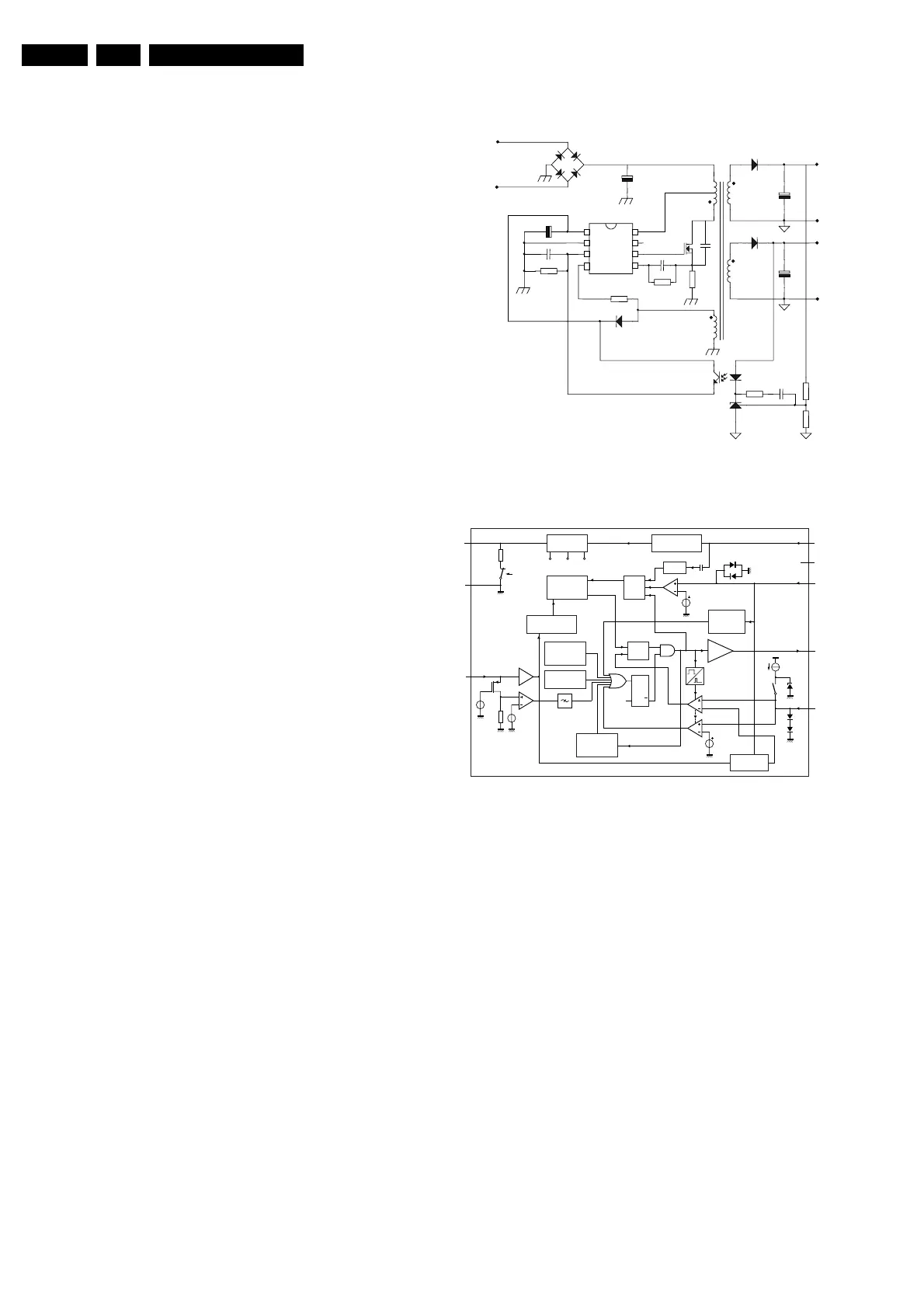
9.6 Power Supply
Figure 9-6 Switched Mode Power Supply standard circuit
Figure 9-7 Internal blockdiagram of the driver IC (TEA1507)
9.6.1 Introduction
The supply is a Switching Mode Power Supply (SMPS). The
frequency of operation varies with the circuit load. This 'Quasi-
Resonant Flyback' behavior has some important benefits
compared to a 'hard switching' fixed frequency Flyback
converter. The efficiency can be improved up to 90%, which
results in lower power consumption. Moreover, the supply runs
cooler and safety is enhanced.
The power supply starts operating when a DC voltage goes
from the rectifier bridge via T5520, R3532 to pin 8. The
operating voltage for the driver circuit is also taken from the
'hot' side of this transformer.
The switching regulator IC 7520 starts switching the FET 'on'
and 'off', to control the current flow through the primary winding
of transformer 5520. The energy stored in the primary winding
during the 'on' time is delivered to the secondary windings
during the 'off' time.
The 'MainSupply' line is the reference voltage for the power
supply. It is sampled by resistors 3543 and 3544 and fed to the
input of the regulator 7540 / 6540. This regulator drives the
feedback optocoupler 7515 to set the feedback control voltage
on pin 3 of 7520.
The power supply in the set is 'on' any time AC power goes to
the set.
Demag4
Ctrl
Gnd
Vcc Drain
HVS
Driver
Sense
3
2
1
5
6
7
8
V
LINE
V
TEA1507
IN
C
IN
V
CC
C
D
R
SENSE
C
SS
R
SS
V
OUT
N
S
N
P
N
Vcc
CL 16532020_074.eps
120401
SUPPLY
MANAGEMENT
internal
supply
UVLO start
M-level
V
CC
1
2
3
GND
S1
CTRL
FREQUENCY
CONTROL
VOLTAGE
CONTROLLED
OSCILLATOR
LOGIC
LOGIC
OVER-
VOLTAGE
PROTECTION
OVERPOWER
CL 16532020_073.eps
060701
PROTECTION
short
winding
soft
start
S2
OVER-
TEMPERATURE
PROTECTION
SQ
R
UVLO
Q
MAXIMUM
ON-TIME
PROTECTION
POWER-ON
RESET
−1
VALLEY
TEA1507
100 mV
clamp
DRIVER
START-UP
CURRENT SOURCE
0.75 V
0.5 V
5
I
sense
6
DRIVER
4
DEM
8
DRAIN
7
HVS
n.c.
OCP
LEB
blank
I
ss
2.5 V
burst
detect
www.freeservicemanuals.info
Published in Heiloo Holland
 Loading...


