3-2
SERVICE POSITIONS
Service position A
Service position C
Service position B
Note: In some service positions the components or copper patterns of one board may risk touching its neighbouring pc
boards or metallic parts. To prevent such short-circuit use a piece of hard paper or other insulating material between them.
3-2
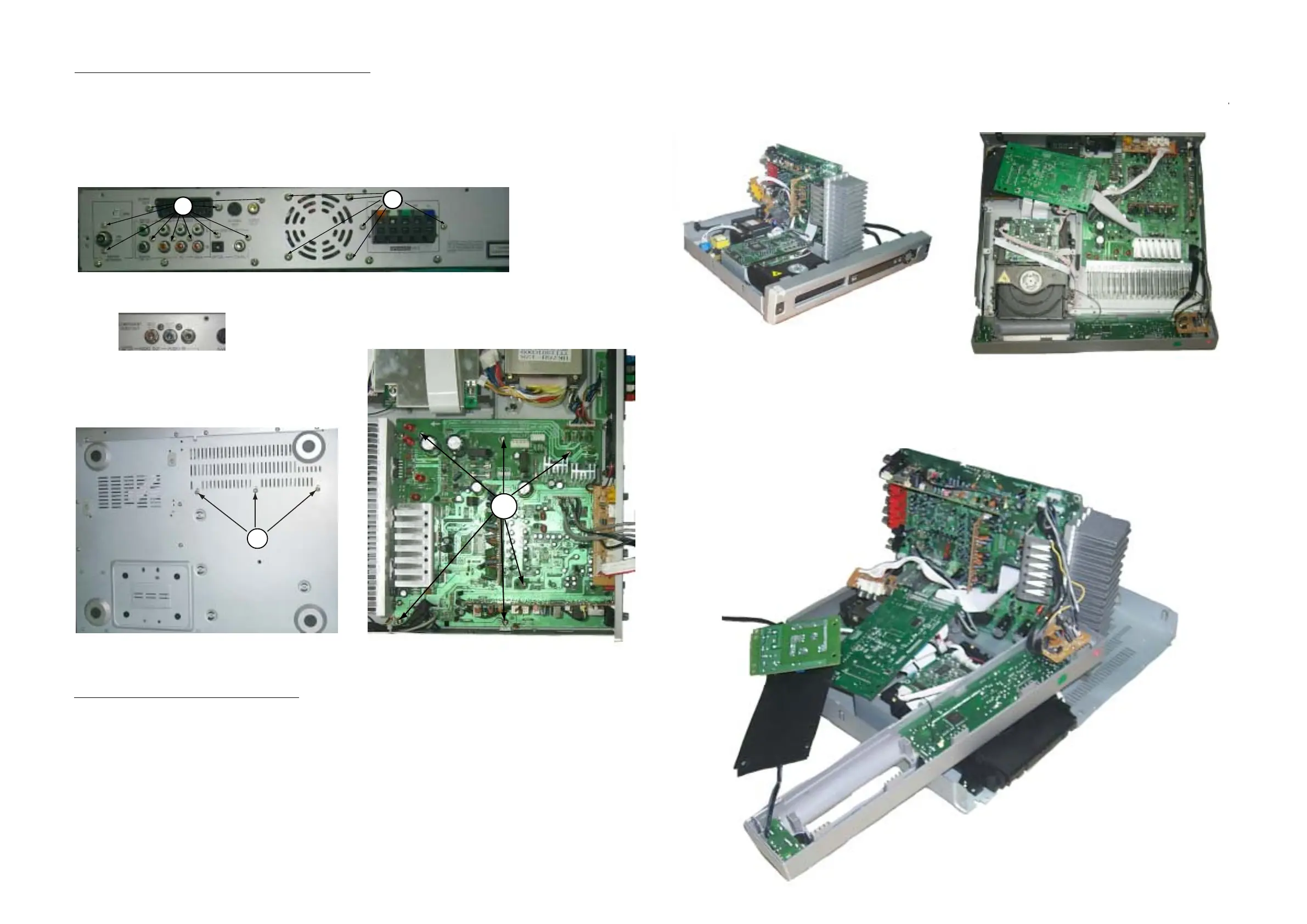
Dismantling of the Main Board (include Tuner & Surround Board)
1) Loosen 6 screws F on the top of main board as shown in figure 7.
2) Loosen 10 screws C at the back panel as shown in figure 8.
3) Loosen 3 screws D on the bottom cover as shown in figure 9.
4) Remove all connectors on tuner, surround, RGB/Scart & main board.
Figure 9
D
Figure 8
Dismantling of the Speaker Jack Board & Fan
1) Loosen 6 screws E at the back panel as shown in figure 8.
2) Remove all connectors at speaker jack and Fan.
F
Figure 7
C
E
RGB Jack use for LX3000/21S/21L/30S;
LX3500/37S/21R/21H
Scart Jack use for LX3000/22S only