EasyManua.ls Logo

Philips MCM7/22 Service Manual

Philips MCM7/22
73 pages
To Next Page IconTo Next Page
Page #1 background imageLoading...
Page #1 background image
CLASS 1
LASER PRODUCT
Service Manual
Service
Service
Service
Service
Service
MCM7/22/37
TABLE OF CONTENTS
Page
Location of pc boards & Version variations ................1-2
Technical Specifications .............................................1-3
Measurement setup ....................................................1-4
Service Aids, Safety Instruction, etc...........................1-5
Disassembly Instructions & Service positions .............. 2
Service Test Program .................................................3-1
Set Block diagram ......................................................4-1
Set Wiring diagram .....................................................5-1
Front Board .................................................................... 6
ECO6 Tuner Board : Systems Non-Cenelec............. 7A
Systems Cenelec..................... 7B
Mains Board................................................................... 8
ETF8 Tape Module ........................................................ 9
Universal Loader ......................................................... 10
Combi & Regulator Boards.......................................... 11
Set Mechanical Exploded view & parts list ................. 12
©
Copyright 2004 Philips Consumer Electronics B.V. Eindhoven, The Netherlands
All rights reserved. No part of this publication may be reproduced, stored in a retrieval system or
transmitted, in any form or by any means, electronic, mechanical, photocopying, or otherwise
without the prior permission of Philips.
Published by BB 0411 Service Audio Printed in The Netherlands Subject to modification
GB
3139 785 30610
Micro System
Version 1.0
Question and Answer IconNeed help?

Do you have a question about the Philips MCM7/22 and is the answer not in the manual?
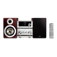
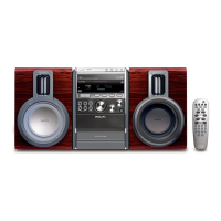
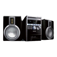
Philips MCM7/22 Specifications

General IconGeneral
TypeMicro Hi-Fi System
Speaker Type2-way
TunerFM
Number of Discs1
Audio formatsMP3, WMA
Output power20 W RMS
RDSYes
CD PlayerYes
BluetoothNo
Disc PlaybackCD
ConnectivityUSB

Summary

SPECIFICATIONS

General Specifications

Overall electrical and physical specifications of the micro system.

Tuner Specifications

FM and MW tuning range, sensitivity, and selectivity.

Amplifier Specifications

Output power, frequency response, and special features.

MEASUREMENT SETUP

Tuner Measurement Setup

Procedures for measuring FM and AM tuner performance.

CD/Recorder Measurement Setup

Measurement procedures for CD and cassette recorder sections.

HANDLING CHIP COMPONENTS

Chip Component Handling Procedures

Guidelines for safe dismounting, mounting, and precautions.

SAFETY WARNINGS

ESD and Laser Safety Precautions

Warnings and instructions regarding ESD, laser radiation, and general safety.

DISMANTLING INSTRUCTIONS

Cover Cassette and Universal Loader Dismantling

Step-by-step guide to remove the cassette cover and universal loader.

Universal Loader Detachment

Instructions for detaching the universal loader from the bracket.

Front Panel Assembly Detachment

Instructions for detaching the front panel from the chassis.

SERVICE TEST PROGRAM

SET BLOCK DIAGRAM

SET WIRING DIAGRAM

FRONT BOARD

DISPLAY BOARD - COMPONENT LAYOUT

DISPLAY BOARD - CHIP LAYOUT

DISPLAY BOARD - CIRCUIT DIAGRAM PART 1

DISPLAY BOARD - CIRCUIT DIAGRAM PART 2

TOP KEY BOARD - COMPONENT LAYOUT

CONTROL BOARD - COMPONENT LAYOUT

CONTROL BOARD - CIRCUIT DIAGRAM PART 1

CONTROL BOARD - CIRCUIT DIAGRAM PART 2

EEPROM BOARD - COMPONENT LAYOUT

KARAOKE BOARD - COMPONENT LAYOUT

KARAOKE BOARD - CIRCUIT DIAGRAM

ECO6 Tuner Board

TUNER BOARD ECO6 / SYSTEMS NON Cenelec

TUNER ADJUSTMENT TABLE

TUNER BOARD ECO6 / SYSTEMS-CENELEC

MAINS BOARD

MAINS BOARD - COMPONENT LAYOUT

MAINS BOARD - CHIP LAYOUT

MAINS BOARD - CIRCUIT DIAGRAM

ETF8 TAPE MODULE

TAPE ADJUSTMENT & CHECK TABLE

COMPONENT LAYOUT

CIRCUIT DIAGRAM

Universal Loader

Service Hints

Troubleshooting advice for skipping tracks and lens cleaning.

Laser Current Measurement

Procedure for measuring laser current and interpreting results.

BLOCK DIAGRAM

CD MAIN BOARD

Block diagram of the CD main board with signal processor and drivers.

COMBI & REGULATOR BOARDS

REGULATOR BOARD - COMPONENT SIDE VIEW

REGULATOR BOARD - COPPER SIDE VIEW

REGULATOR BOARD - CIRCUIT DIAGRAM

COMBI BOARD

COMBI CIRCUIT - SOURCE SELECTOR PART

COMBI CIRCUIT - AMPLIFIER PART

SET MECHANICAL EXPLODED VIEW

Related product manuals