400
-:a
"l
I
I
l
l
l
l
l
l
l
l
l
l
l
l
I
l
I
l
I
lo
29
Output
The output signal of the ADC
(DATA)
is a square
wave which
is
determined by the charging/discharging
times
of the capacitor. Charging the capacitor will
give
a logic 1 and
discharging willgive a logic 0 of
the DATA
signal.
ln
this
way
the analog signal is converted into a block siqnal
which is dependent to the charging
and
discharging times of the capacitor.
Logic
'1
of
the
DATA signal
means
up and
logic
0 means
down
counting
of clockpulses.
As the
charging
and
discharging times differ,
a counting
result is lcft in
the counter
after on cycle, Within
one measurement
(two
measuring
periods)
a number of cycles are made. The total result of the counter
after one measurement
is
proportionai
to the unknown input voltage
Vx.
Note: For every value
of Vx a certain
number
of charging/discharying
cycles of which
also the times are
different are made within a measurement.
When measuring the DATA signal
due
to the varying
pattern
only can be seen
if a data signal
is
present
and how the counter is counting
(up
or down).
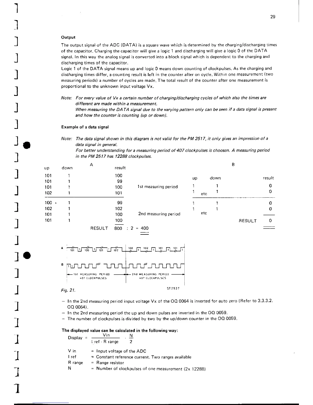
Example
of a data signal
Note:
The data signal shown in this diagram is
not
valid
for
the
PM 2517, it only
gives
an
impression of a
data signal in
general.
For
better understanding for a measuring
period
of 407 clockpulses
is
choosen.
A measuring
period
in
the
PM
2517 has
12288
clockDulses.
up
101
101
101
102
d own
1
1
1
I
result
100
99
'100
101
resu lt
0
0
'lst
measuring
period
2nd measuring
period
up down
1l
1.r"1
100
102
101
101
99
102
100
100
RESULT 8OO:2=
o
0
RESULT
O
-
In
the 2nd measuring
period
input
voltage
Vx of the
OO
0064 is inverted
for auto zero
(Refer
to 3.3.3.2.
oo
0064).
-
In
the 2nd measuring
period
the up and
down
pulses
are
inverted in the OQ 0059.
*
The number
of clockpulses is
divided by
two
bV the up/down counter
in the OO 0059.
The displayed
value can
be
calculated in the Iollowing
way:
Vin
N
I ref
-
R
range 2
V
in
=
Input
voltage of the
ADC
I ref
=
Constant reference
current. Two ranges available
R
range
=
Range resistor
N
=
Number
of clockpulses of
one measurement
l2x
12288)
5T
2537
.I
.I
I
1
MEA5IJFING PER]OO I'I€ A5URING
P€R
OD