-T
Ll
l-l
32
3.3.4.
Digital
section
3.3.4.1.
General
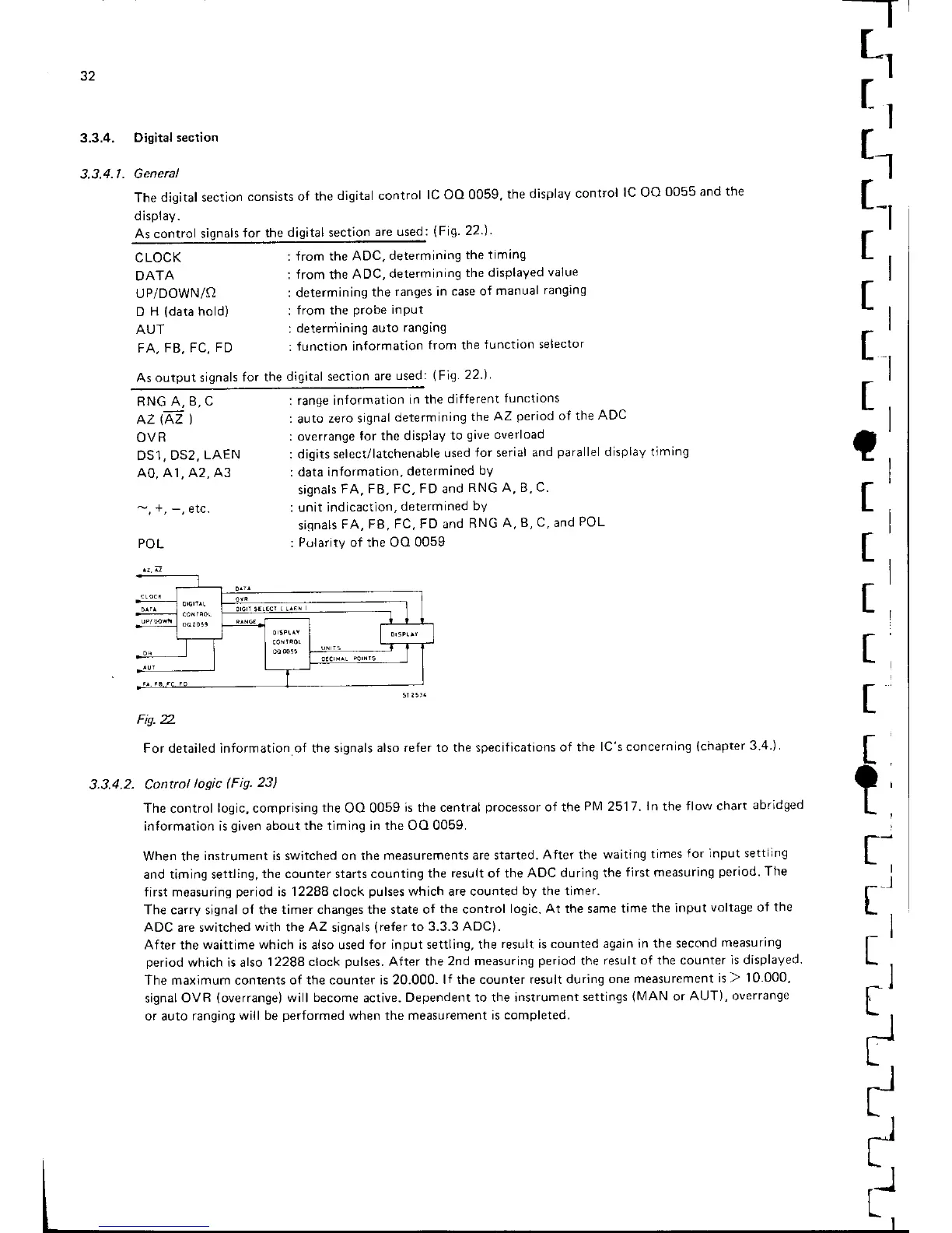
ThedigitalsectionconsistsofthedigitalcontrollCOOOO5g,thedisplaycontrollCOO0055andthe
display.
As control signals
for the
digital section
are used:
(Fig
22
)'
t1
t-l
Il
It
t,
CLOCK
DATA
UP/DOWN/O
D
H
(data
hold)
AUT
FA,
FB, FC,
FD
:
from
the
ADC.
determining
the
timrng
:
from
the
ADC,
determining
the
displayed
value
: determining
the
ranges in
case of
manual
ranglng
:
from the
probe
input
:
determining auto
ranging
:
function in{ormation
from the
Junction
selector
As output signals
for the
digital section
are
used:
(Fig
22.)
RNG
A, 8, C
OVR
DS1.
DS2,
LAEN
AO, 41, 42,
A3
POL
:
range inlormation
in the different
functions
:
auto
zero signal
determining
the
AZ
period
of the
ADC
: overrange
for the display
to
qave
overload
:
digits
select/latchenable
used
Ior
serial
and
paralle
display timing
: data information,
determined
bY
signals
FA, FB, FC,
FD
and
RNG A, B,
C
: unit indicaction,
determined
bY
siqnals
FA, FB,
FC, FD and
RNG
A, B, C, and
POL
:
PolaritV of the OO
0059
I
_l
t
e
t
t
t
t
t
t
t
t
t
Fis. 2.
For detailed information of the signals
also refer to the specifications
of the
lC's concerning
(chapter
3.4.)
3.3.4.2- Control
logic
(Fig.23)
The
control
logic, comprising
the
OO 0059
is the central
processor
of the
Pl\,4
2517.
ln
the
flow chart
abridged
information is
given
about
the timing in the OO 0059.
When the
instrument is switched on the
measurements are started.
After the
waiting times
{or input settllng
and timing settling,
the counter starts counting
the result of the
ADC during the
first measuring
period.
The
first measuring
period
is
12288
clock
pulses
which are counted
by the timer.
The carry signal ol the
timer changes the state of
the
control
logic.
At
the same
time
the input
voltage of
the
ADC are switched
with
the
AZ
signals
(refer
to 3.3.3
ADC)
.
After the
waittime which
is also used
for input settling, the
result is counted again
in the second
measuring
period
which is also
12288 clock
pulses.
After the
2nd measuring
period
the
result of the counter
is displaVed
The maximum contents of
the counter is 2O.OOO-
lf the counter result during
one measurement
is ) 10-000,
signal
OVR
(overrange)
will become
active.
Dependent to the instrument
settings
(NrlAN
or
AUT), overrange
or auto ranging
will be
performed
when the measurement
is completed.
r'
*l
rl
t-
tl
I
I
-
I
-
:J