I
I
I
I
l
l
l
l
l
l
l
l
l
I
I
l
I
I
I
I
)
I
I
,t
.J
,l
67
FAULT
FINDING
General
Service
hints
lf servicing
has to be carried out the
following
points
should be
taken into account
in
order to avoid
damaging
the instrument.
-
Take care to avoid short'circuits
with measuring clips and hooks
if
the
instrument is
switched-on,
especially
near
the
input
terminals
when high-voltages are
present.
-
Use
miniature
soldering
iron
(35
W max.) with a tin cleaner
or
a
vacuum soldering iron.
-
Use an acid-free solder.
-
When fault-finding, dismantle
the instrument,
unsolder
the battery wires and
loosen the display
board
-
As
the
dismantled
instrument is not very
stable
it is
advised
to use a work
lixing
clamp,
when
measuring
or
replacing
parts.
-
After
repair
the instrument should be calibrated again.
Faull.f inding
procedure
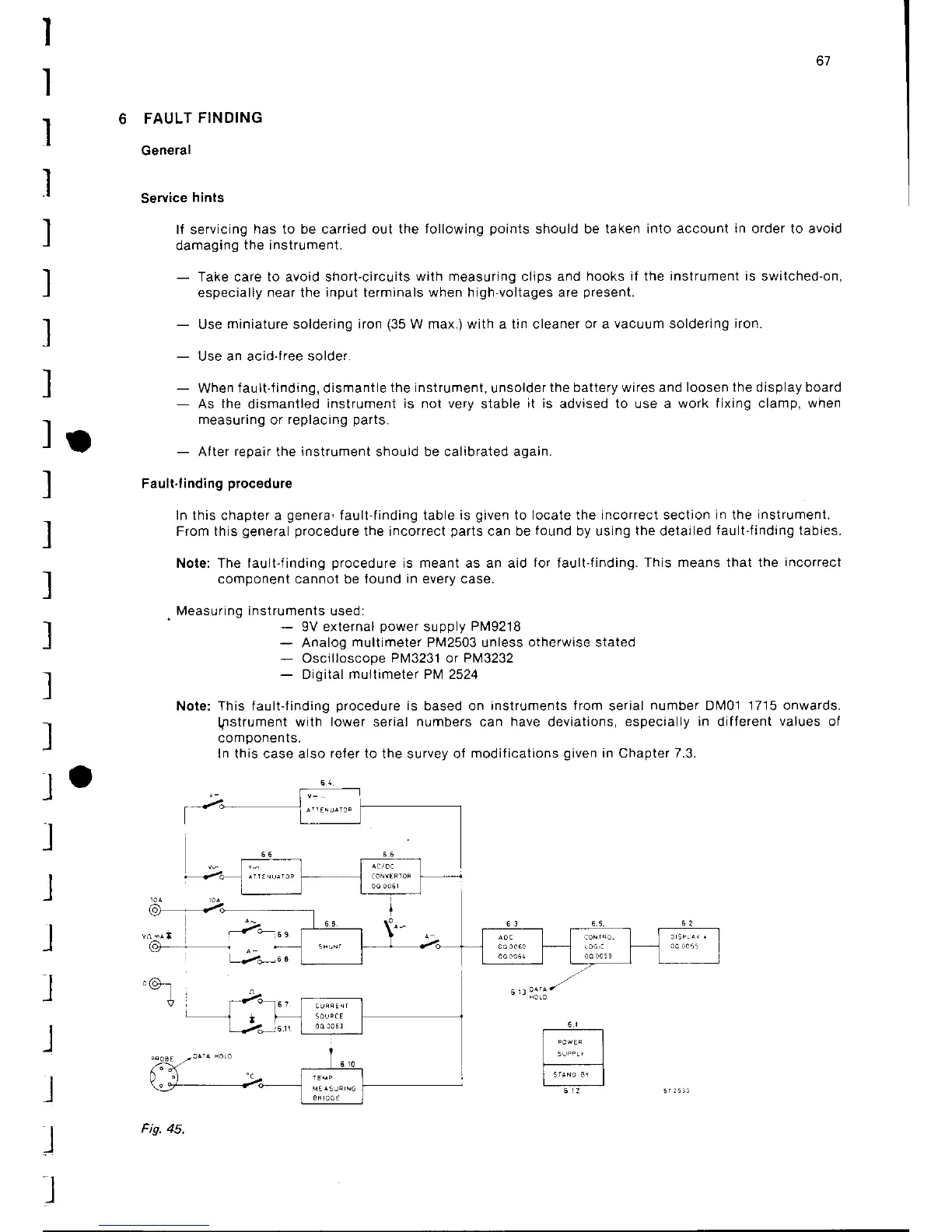
ln this chapter a
genera,
fault-finding table is
given
to locate the incorrect section in the
inslrument.
From this
general procedure
the incorrect
parts
can be
found
by using
the
detailed
fault-finding tables.
Nole: The fault-iinding
procedure
is meant as an aid
for
fault-finding.
This means that the
incorrect
component cannot tle found
in
every case.
.
Measuring instruments
used:
-
9V external
power
supply
P1v19218
-
Analog multimeter PM2503 unless otherwise stated
-
Oscilloscope PN4323'1 or P1v13232
-
Digital multimeter Pl\4 2524
Note: This faultJinding
procedure
is based on
instruments from
serial
number Dl\401 1715 onwards.
l.nstrument
with
lower
serial
numbers
can
have
deviations,
especially in diflerent
values
of
co
m
pone
nt s.
In this case also
refer
to the survey of
modifications
given
in Chapter 7.3.
2*'""
6,3:älä
t-19,45.