33
I
I
I
Explanation of states
I
J
WAIT
|
=
Fixed waiting,96 clockpulses.
I
The time is used
for input
settling
I
Wntf
Z
=
Variable waiting time. The timing
of the input signal
has to meet a
certain condition
before a measurement is started.
(lMax.
10 clock
pulses).
_t.
I
lst
and
2nd
=
12288 clock
pulses
determined by the timer
J
fulEASU R ING
_
PER
rOD
I
J
SfOp
=
End
of the
measurement, reset U/D
counter
RANGING
=
lvlanual or automatic ranging command
I
coNlt\rAND
J
RANGING
=
Selecting the correct measuring
range.
I
J
3.3.4.3.
Control signals
(Fig.
54 and 22)
Clock
The
clocksignal
(80
Hz
. . .
120
kHz)
determines the timing
in the instrument and
is counted
by a
-
12888
timer.
The
output
of the timer is supplied to the control logic. On
this signal the control
logic
will take action
viz:
switching
of the signal AZ,
AZ
by
which
the
input of the ADC is switched
(refer
to
ADC
3.3.3.).
Data
The duty cycle of the
data
signal is dependent to
the height of the input
voltage supplied to
the
PM
2517
(refer
to ADC 3.3.3.). The
data
signal is supplied
via the UP/DOWN control to
the UP/DOWN counter.The
UP/DOWN
counter
is counting the clock
F,ulses.
Data signal
logic 1 is count up,
loqic 0 is count
down.
During the 2nd measuring
period
the DATA signal
is inverted inside the OO 0059
UP/DOWN
N/A
.
.ln
case of
manual ranging UP
or DOWN
pulses
from the UP/DOWN circuit are
supplied to
the OO 0059.
ln the
ranging
counter
the
pulses
are
converted into the range code I x
depress is one range up
or down.
In the ranges
V
. . . and V
\
the number
of
ranges
is four. BV means
of signal
,f)
this
is
extended
to six.
Aut
By
means of a
logic
1 ot signal
AUT
(auto
ranging),
which
is
generated
by the UP/DOWN/AUT
circuit,
the
digital
section is switched to auto
ranging
mode. When the
result of the UP/DOWN counter
is larger
than 10.000
in
a
range
{V-_
,
V- or k()
)
then the control
logic switched automatically to a
higher range.
This is repeated
untill the
contents
of the
counter
is less than 10.000.
The same happens
during down
ranging is the automode the
down level for the
UP/DOWN counter
is 900.
Down ranging is repeat untillthe contents of the counter is larger than
900.
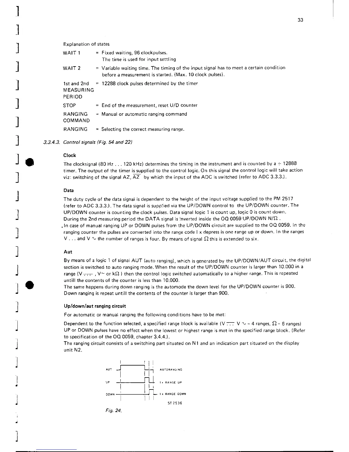
Up/down/aut ranging circuit
For
automatic
or manual ranging the following conditions have to
be met:
Dependenttothefunctionselected,aspecifiedranqeblockisavailable(V:-;:V\,=4ranges,O=6ranges)
UP or DOWN
pulses
have no
effect when the lowest
or
highest range is met in the specified range block.
(Reler
to
specification of
the
OO 0059, chapter 3.4.4.).
The ranging
circuit
consists of a switching
part
situated
on N1
and
an indication
part
situated
on the display
unit N2.
Fis.24.
5T25t6