PM
2517E
DM 02
4926
-
DM 04
10491
PM25\7X
DM 0r 3051
-
DM 04 86il
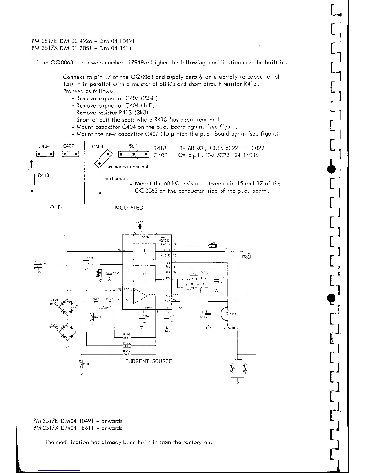
lf the OQ0063 hos
q
weeknumber of7919or higher the following
modificotion must be built in,
Connect to
pin l/
of the OQ0063
ond
supply
zero
$
on electrolytic copocitor
of
15P
F
in porollel with o
resistor of 68
kQ ond
short
circuif
resistor R413.
Proceed
os
follows:
-
Remove
copocitor C407
(22nF
)
-
Remove
copociior C404
(1nF)
-
Remove resistor R413
(3k3)
-
Short circuii the spots
where R4l3 hqs been removed
-
Mounl copocitor C404 on the
p.c.
boord
ogoin.
(see
figure)
-
Mount the new
copocitor
C407
(15 p
f)on the
p.c.
boord
ogoin
(see
figure) '
t"
t;
I
t,.,
[,
r'
I
:r
I
a
Ir
5;
r;
[1
t;
r;
r,
:r
tJ
c404
F---n
R
413
short
OLD
PM 2517E
DM04
10491
-
onwqrds
PM
2517X DM04 8611
-
onwords
The
modificqtion
hos
olreody been built
R4lB R= 68
ka, CRl6 5322
lll
30291
C407
C=l5p
F, 10V
5322
124 14036
wrres in
cne
hole
clrcurr
-
Mount fhe 68 kQ resistor befween
pin
15 ond lZ
of the
OO0063
ot the conductor side of the
p.c.
boord.
NNODIFIED
CURRENT SOURCE
c401
F-l
15uF
fr
T
-l:,.
I
c404
in from the foctory
on.