Mechanical Instructions
EN 13Q548.1E LA 4.
2009-Apr-03
4.2 Service Positions
For easy servicing of this set, there are a few possibilities
created:
• The buffers from the packaging.
• Foam bars (created for Service).
4.2.1 Foam Bars
Figure 4-9 Foam bars
The foam bars (order code 3122 785 90580 for two pieces) can
be used for all types and sizes of Flat TVs.
See figure Figure 4-9
for details. Sets with a display of 42" and
larger, require four foam bars [1]. Ensure that the foam bars
are always supporting the cabinet and never only the display.
Caution: Failure to follow these guidelines can seriously
damage the display!
By laying the TV face down on the (ESD protective) foam bars,
a stable situation is created to perform measurements and
alignments. By placing a mirror under the TV, you can monitor
the screen.
4.3 Assy/Panel Removal
The instructions apply to the 8000 series (Roadrunner - with
AmbiLight).
4.3.1 Rear Cover
Warning: Disconnect the mains power cord before you remove
the rear cover.
Note: it is not necessary to remove the stand while removing
the rear cover.
1. Remove all screws of the rear cover.
2. Lift the rear cover from the TV. Make sure that wires and
flat coils are not damaged while lifting the rear cover from
the set.
4.3.2 Speakers
Each speaker unit is mounted with two screws.
When defective, replace the whole unit.
4.3.3 Ambi Light
Each Ambi Light unit is mounted on a subframe. Refer to
Figure 4-10
for details.
Figure 4-10 Ambi Light unit
1. Remove the Ambi Light cover [1].
2. Unplug the connector(s) [2].
3. Remove the subframe [3].
4. The PWB can now be taken from the subframe.
When defective, replace the whole unit.
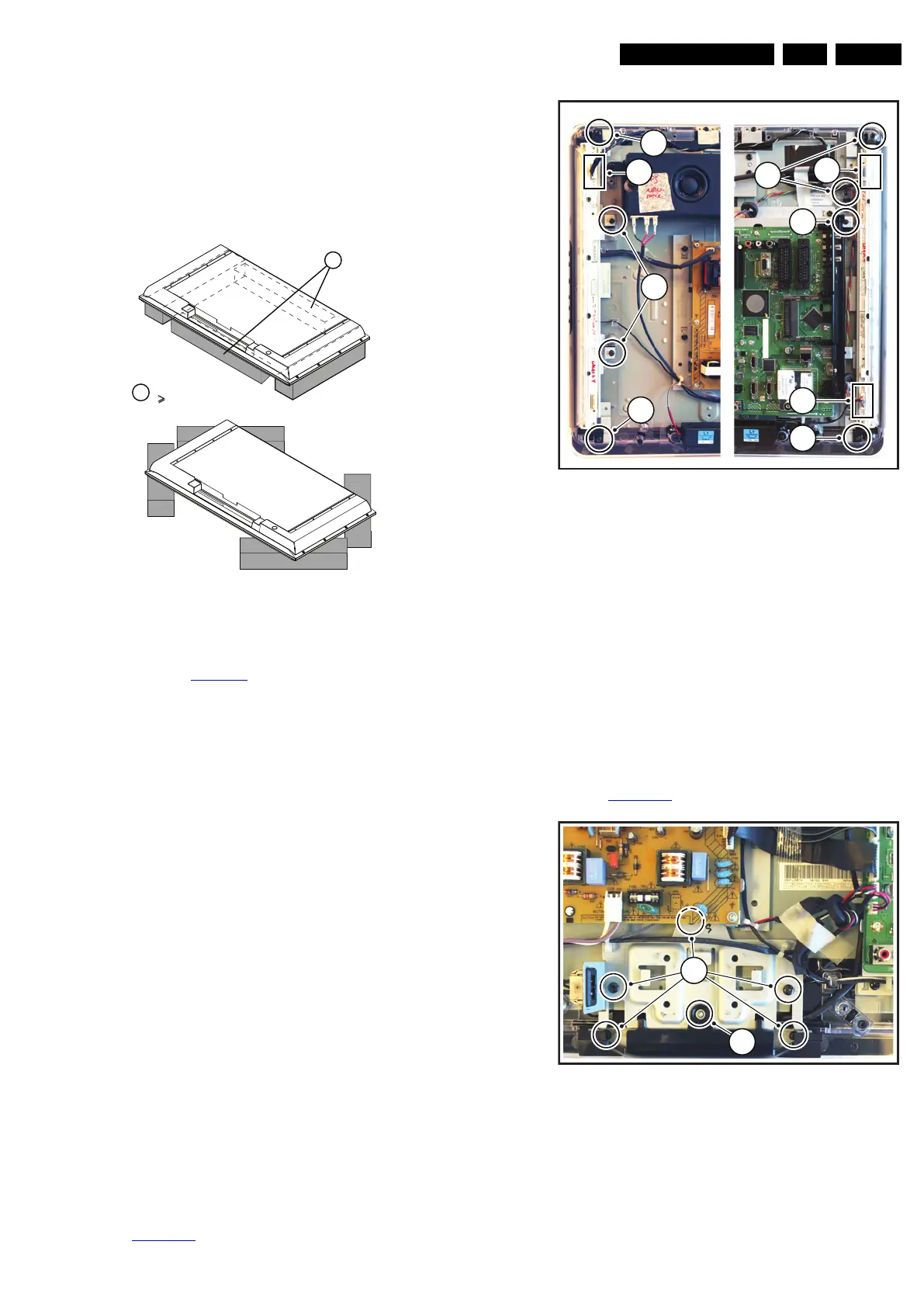
4.3.4 Main Supply Panel
1. Unplug all connectors.
2. Remove the fixation screws.
3. Take the board out.
When defective, replace the whole unit.
4.3.5 IR & LED Board / Stand Support
Refer to Figure 4-11
for details.
Figure 4-11 IR & LED Board / Stand Support
1. Remove the stand.
2. Remove the IR/LED cover [1].
3. Remove the connectors on the IR/LED board.
4. Remove the fixation screws from the IR/LED board.
When defective, replace the whole unit.
E_06532_018.eps
171106
1
Required for sets
42"
1
18560_408_090401.eps
090402
3
1
2
1
1
3
1
2
2
18560_109_090401.eps
090402
2
1