Circuit Descriptions
EN 48 Q548.1E LA7.
2009-Apr-03
The SPI bus is a synchronous serial data link standard that
operates in full duplex mode.
For debugging purposes, the working principle is given below:
• At startup the controller will read-out matrix data from the
EEPROM devices (via SPI DATA RETURN)
• Before operation, the driver current is set via SPI, with
driver in DC mode
• During normal operation the controller receives RGB-,
configuration-, operation mode- and topology data via I
2
C
• The controller converts the I
2
C RGB data via the matrixes
to SPI LED data
• Via data return the controller receives error data (if
applicable).
Also PWM clock and BLANK signals are generated by the
controller. The controller can be reprogrammed via I
2
C (via
USB). The controller can receive matrix values via I
2
C, which
will be stored in the EEPROM of each AL module via the SPI
bus. The temperature sensor in each AL module controls the
TEMP line; in case of a too high temperature the controller will
reduce the overall brightness.
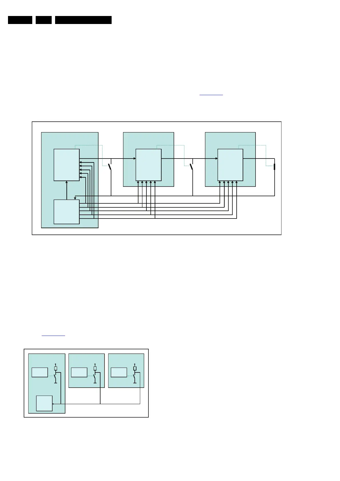
7.8.2 LED driver communication (via SPI bus)
Refer to Figure 7-16
below for signal interfacing between the
ARM controller and the LED drivers on the AL boards, and the
LED drivers and the EEPROMs on the AL boards.
Figure 7-16 SPI communication between ARM controller and LED drivers
The ARM controller communicates with the LED drivers (on
each AL module) via an SPI bus. For debugging purposes, the
working principle is given below:
• Data from the ARM controller is linked through the drivers,
which are connected in cascade
• SPI CLK, SPI LATCH, PROG, BLANK and PWM CLOCK
are going directly from the controller to each driver
• SPI DATA RETURN is linked from the last driver to the
controller: controller decides which driver returns data.
7.8.3 Temperature Control
Refer to Figure 7-17
for signal interfacing between the ARM
controller and the temperature sensor on the AL boards.
Figure 7-17 Communication between ARM controller and
temperature sensor
Each AL board is equipped with a temperature sensor. If one of
the sensors detects a temperature over the threshold, the
TEMP line is pulled LOW which results in brightness reduction.
18310_205_090318.eps
090318
Ambilight modu le 1 Am b ilight modu le 2 Amb ilight modu le N
ARM
LED
DRIVER
1
LED
DRIVER
2
LED
DRIVER
N
S PI data in
S o u t S in S o ut S o u tS in
SPI clo ck (SCLK)
SPI latc h (XLAT)
PRO G (VPRG)
BLANK
PW M CLOCK ( GSCLK)
o ut16
o ut16
o ut16
SPI da ta return
18310_206_090318.eps
090318
Ambilight module 1 Ambilight module 2
ARM
TEMP
SENSOR
Vcc
Pu ll-upPull-upPull-up
TEMP
SENSOR
Vcc
Ambilight module N
TEMP
SENSOR
Vcc