32BDL3651T/43BDL3651T
15
17
14
16
15
11
12
13
1 2
RS232
IN
USB
Service Port
USB2.0
MICRO SD
IR-OUT
IR-IN
RS232
OUT
3 4 5 6 7 8
9 10
RJ45
PC LINE IN
DVI-D IN
HDMI 2 IN
HDMI 1 IN
VGA IN
AUDIO OUT
USB B
43BDL3651T
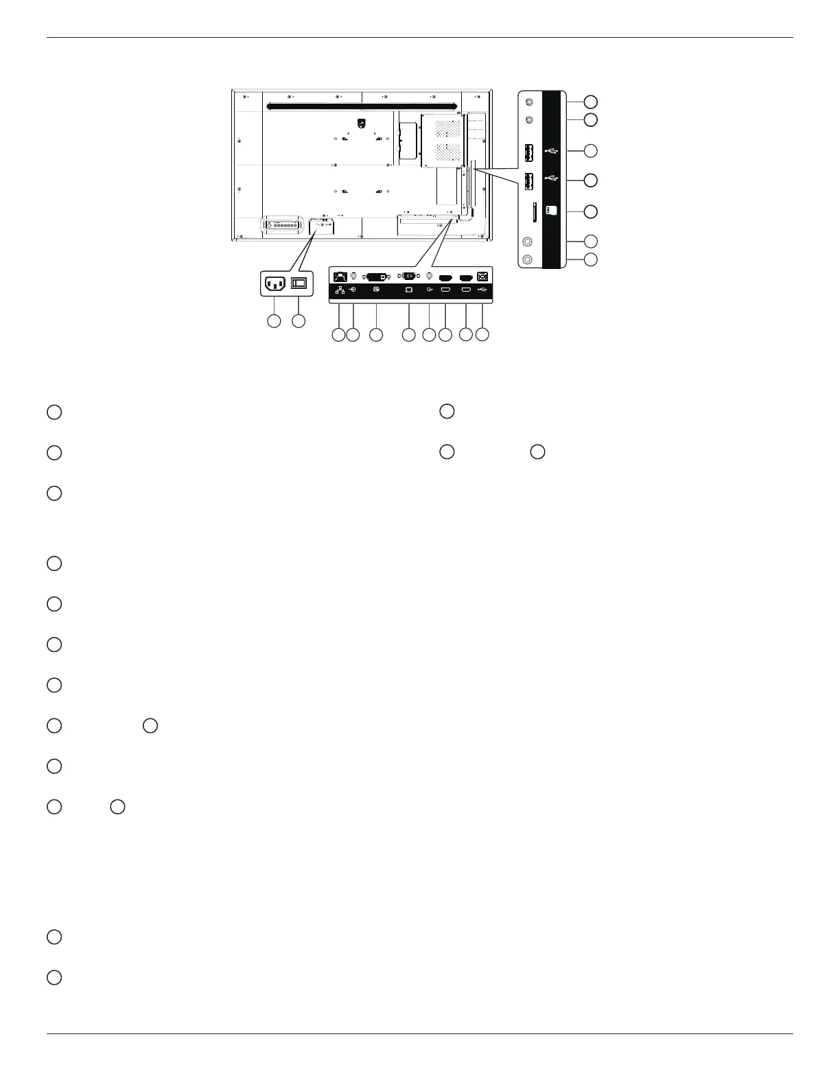
1
AC IN
AC power input from the wall outlet.
2
MAIN POWER SWITCH
Switch the main power between On and O.
3
RJ-45
The LAN control function is used for sending the remote
control signal from the control center in order to install the
optional OPS module.
4
PC LINE IN
Audio input for VGA source (3.5mm stereo phone).
5
DVI-D IN
DVI video input.
6
VGA IN(D-Sub)
VGA video input
7
AUDIO OUT
Audio output for external AV device.
8
HDMI1 IN /
9
HDMI2 IN
Connect to a source device via an HDMI cable.
10
USB-B
Connect to external PC to support touch function
11
IR IN /
12
IR OUT
IR signal input/output for the loop-through function.
NOTES:
• The remote control sensor of this display will stop
working if the jack [IR IN] is connected.
• To remotely control your A/V device via this display,
refer to page 26 for IR Pass Through connection.
13
MICRO SD
Insert a Micro SD card.
14
USB SERVICE PORT
Connect to USB storage for main board Firmware update.
Note: It’s for updating rmware only.
15
USB 2.0 PORT
Connect your USB storage device and service port.
16
RS232 IN /
17
RS232 OUT
Android RS232 network input/output is reserved for
customized protocol usage from System Integrator.

 Loading...