Do you have a question about the Phoenix Contact MCR-F-UI-DC and is the answer not in the manual?
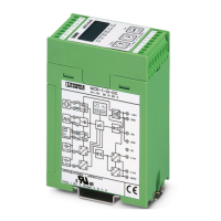
Use shielded conductors, lay cables properly, and connect GND to PE for EMC compliance.
Procedure for handling signal levels above 20V, including jumper removal and terminal connections.
Procedure for handling signal levels above 10V, involving jumper connection and terminal setup.
Describes various display modes for frequency and analog inputs within the set ranges.
Explains the display states for the switching output based on setpoints and signal levels.
Details the various messages displayed during operation, such as 'No input signal'.
Illustrates how the arrow indicates the function to be set within the menu structure.
Step-by-step flowchart for configuring the frequency input parameters and settings.
Details specifications for frequency input range, resolution, and input sources.
Information on the sensor supply voltage and current provided by the module.
Specifies the input frequency limits, peak time, and resolution capabilities.
Defines the signal voltage levels (Vpp) required for different frequency ranges.
Specifies the minimum required pulse length for input signals.
Details specifications for current and voltage input signals and cut-off frequency.
Covers output signal types, maximum signal, load, and switching output details.
Includes supply voltage, current consumption, transmission error, and temperature coefficient.
Lists conformity to directives like EMC and relevant approvals like UL.
| Brand | Phoenix Contact |
|---|---|
| Model | MCR-F-UI-DC |
| Category | Transducer |
| Language | English |