PRODUCT OVERVIEW
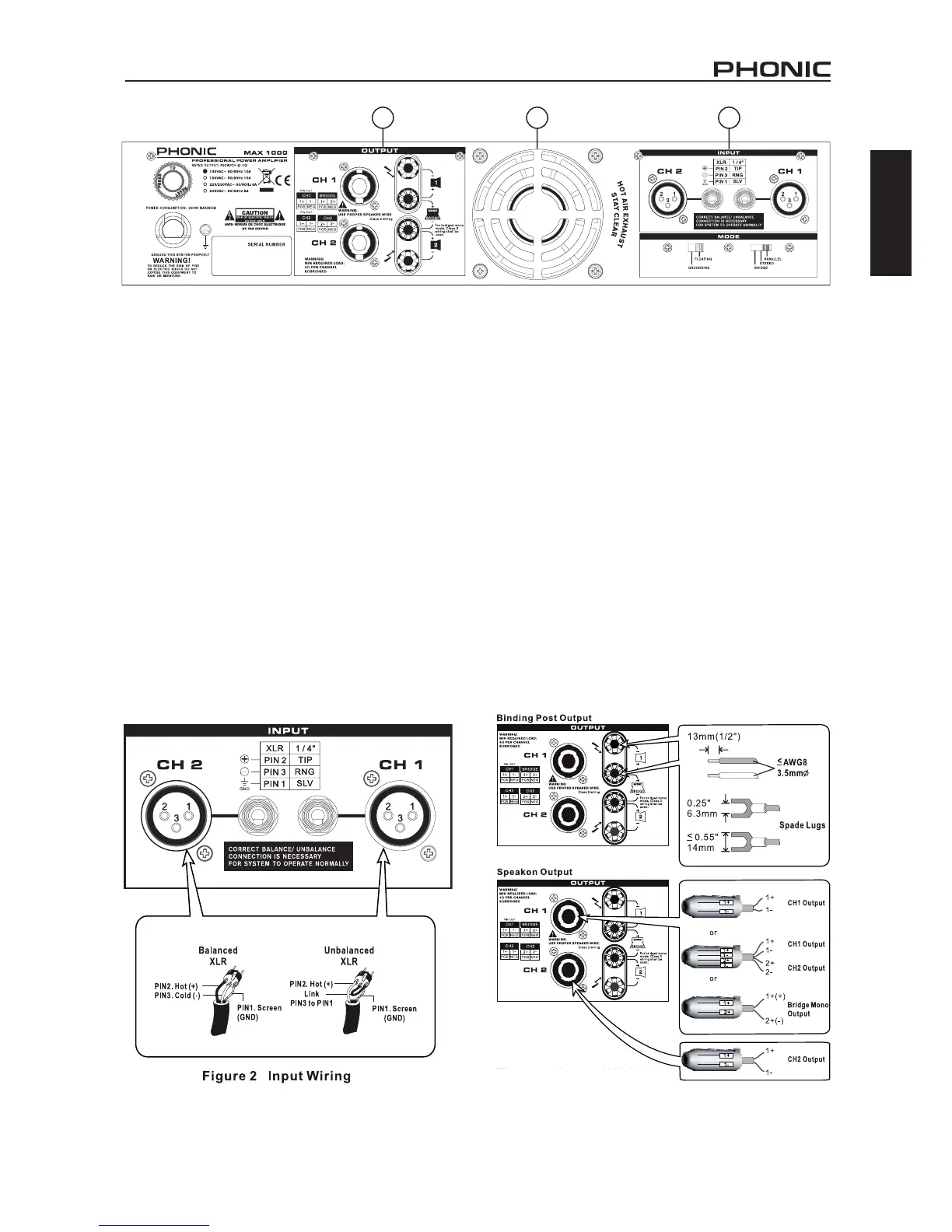
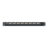
REAR PANEL
1. HEAT VENTILATION
This unit comes with variable speed fan that auto-adjusts
fan speed depending on the temperature of the machine
during operation. Be sure not to obstruct the heat vents in
any way. This will ensure the amplier is always properly
ventilated.
CONNECTIONS
2. INPUT
With these balanced XLR and 1/4” input jacks, you can use
any XLR or 1/4” phone jack connector. These input jacks
accept balanced and unbalanced inputs. When sending
unbalanced signals, the 3rd pin and the 1st pin of the XLR
connector should be connected (see Figure 2).
3. OUTPUT
Binding posts and speakon connectors make up the unit’s
output section. Loudspeakers can easily be connected
using banana plugs, spade lugs, bare wires or speakon
connector. More people prefer using speakon than other
connectors because it’s the least likely to be disconnected
by accident or cause electrical shock. Because speakon
comes with four wires inside, you can connect to two speak-
ers with only one channel output. Be careful when making
connections since improper connecting could cause the
unit to short circuit. The minimum impedance setting for
STEREO and PARALLEL operation is 4 ohm, while 8 ohm
is the minimum for BRIDGE MONO (see Figure 3).
3 1 2
Figure 3 Output Wiring